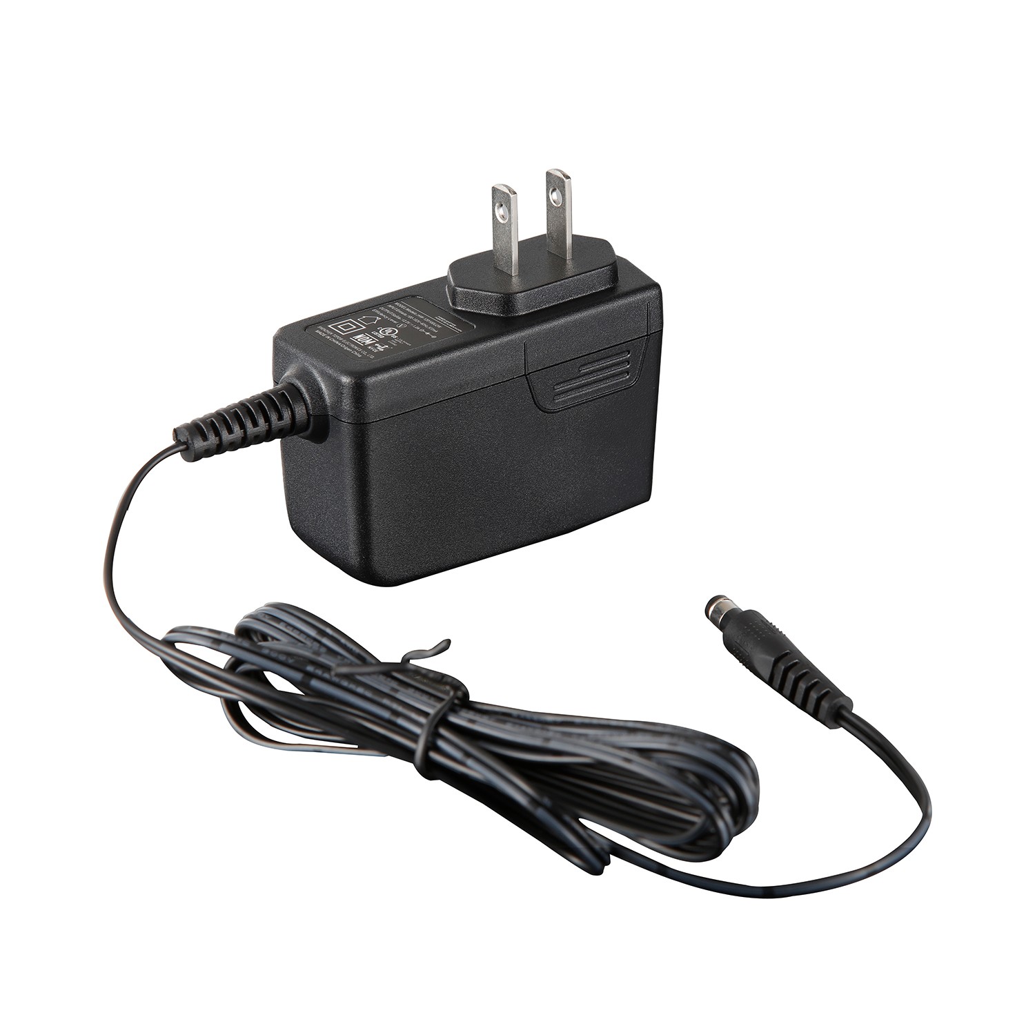

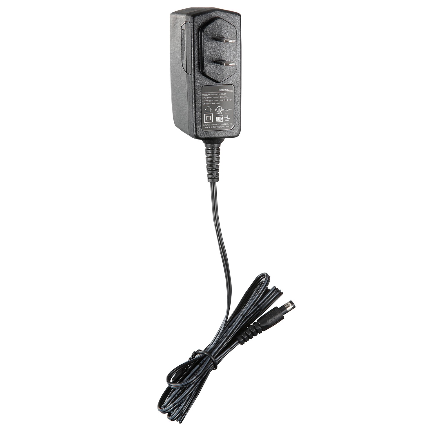
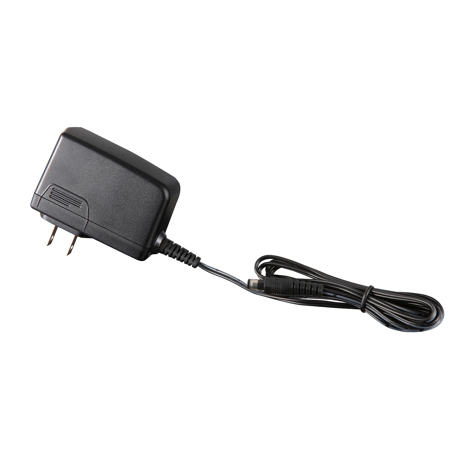
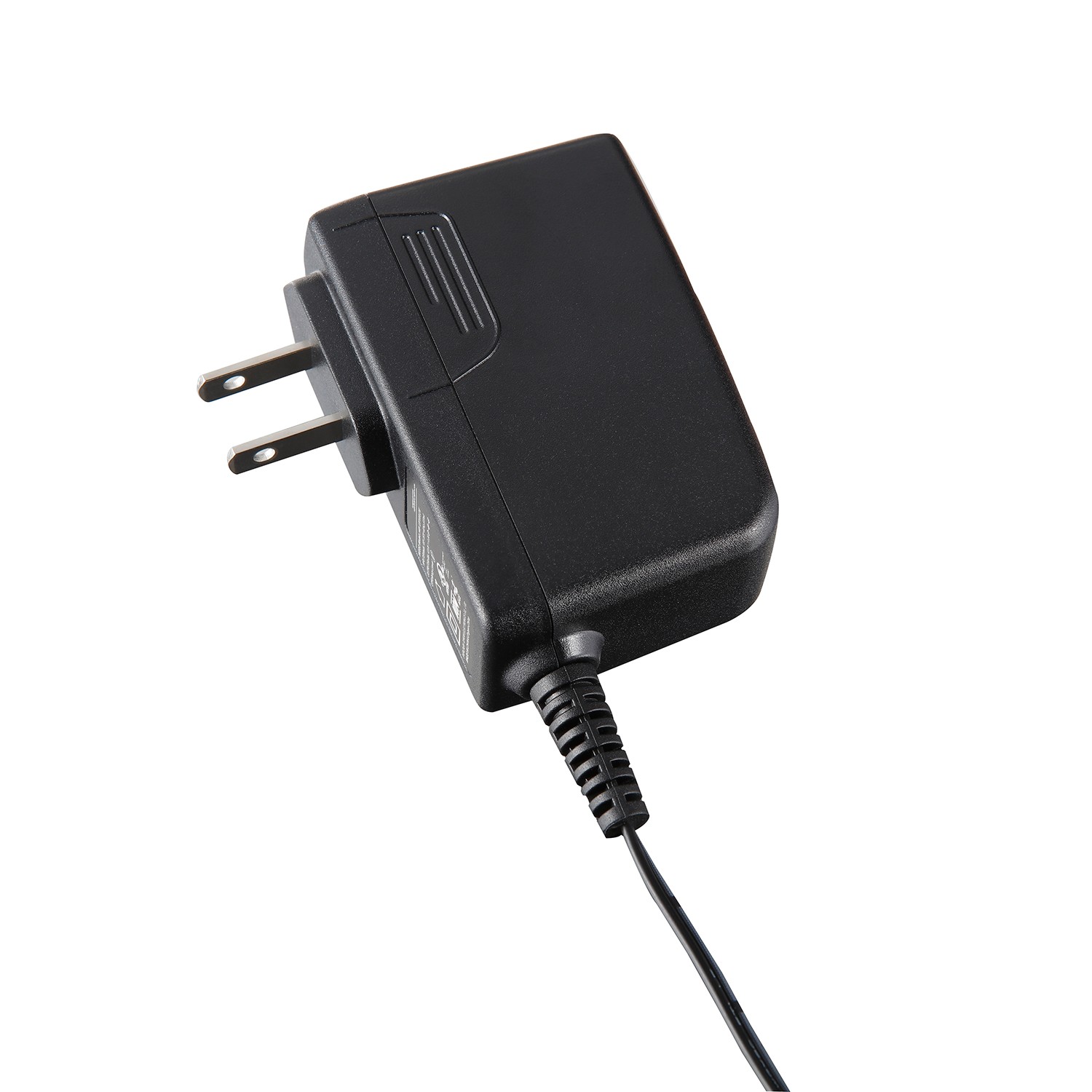
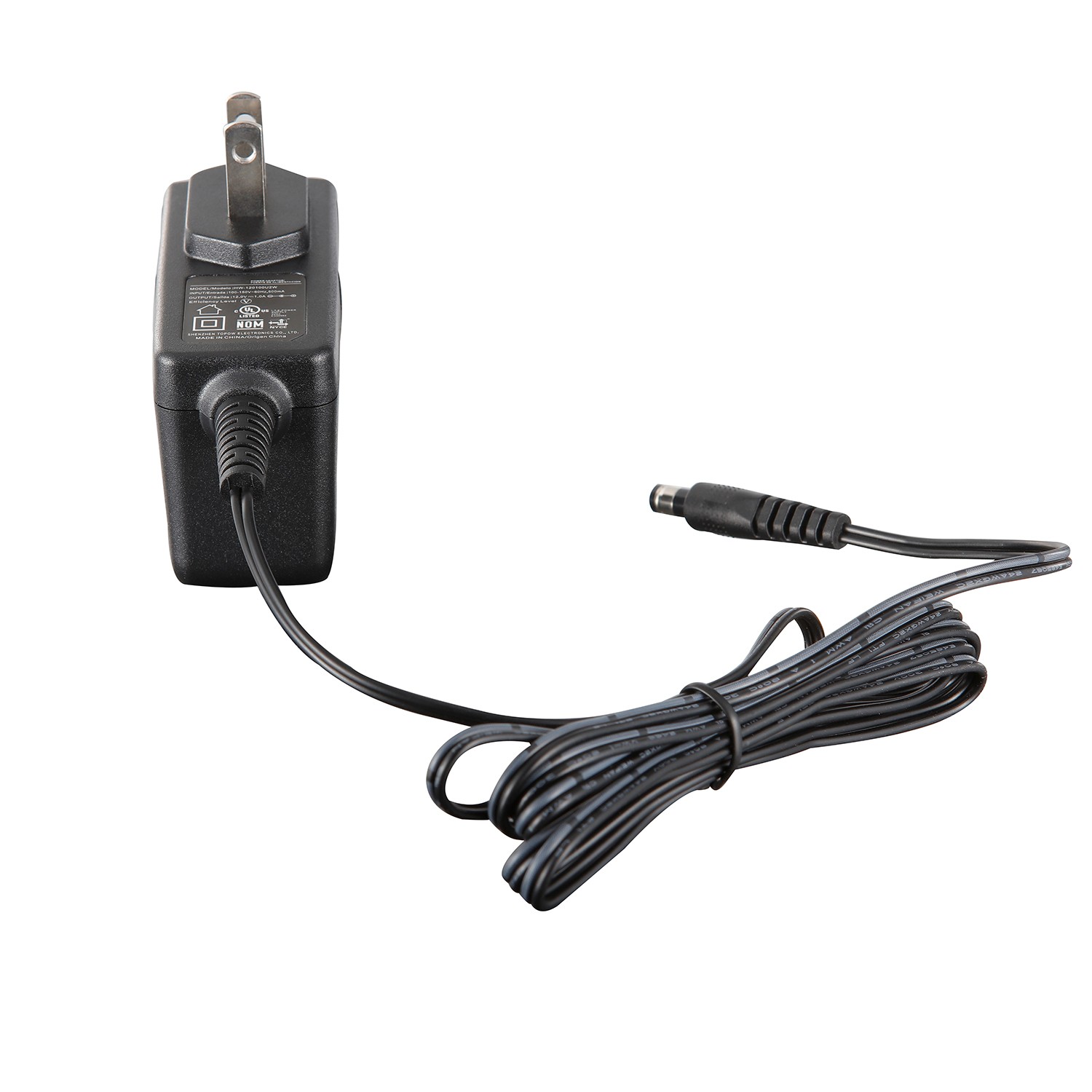
Appearance color: black
Pin type: wall-mounted vertical, US standard
Output power: 12W
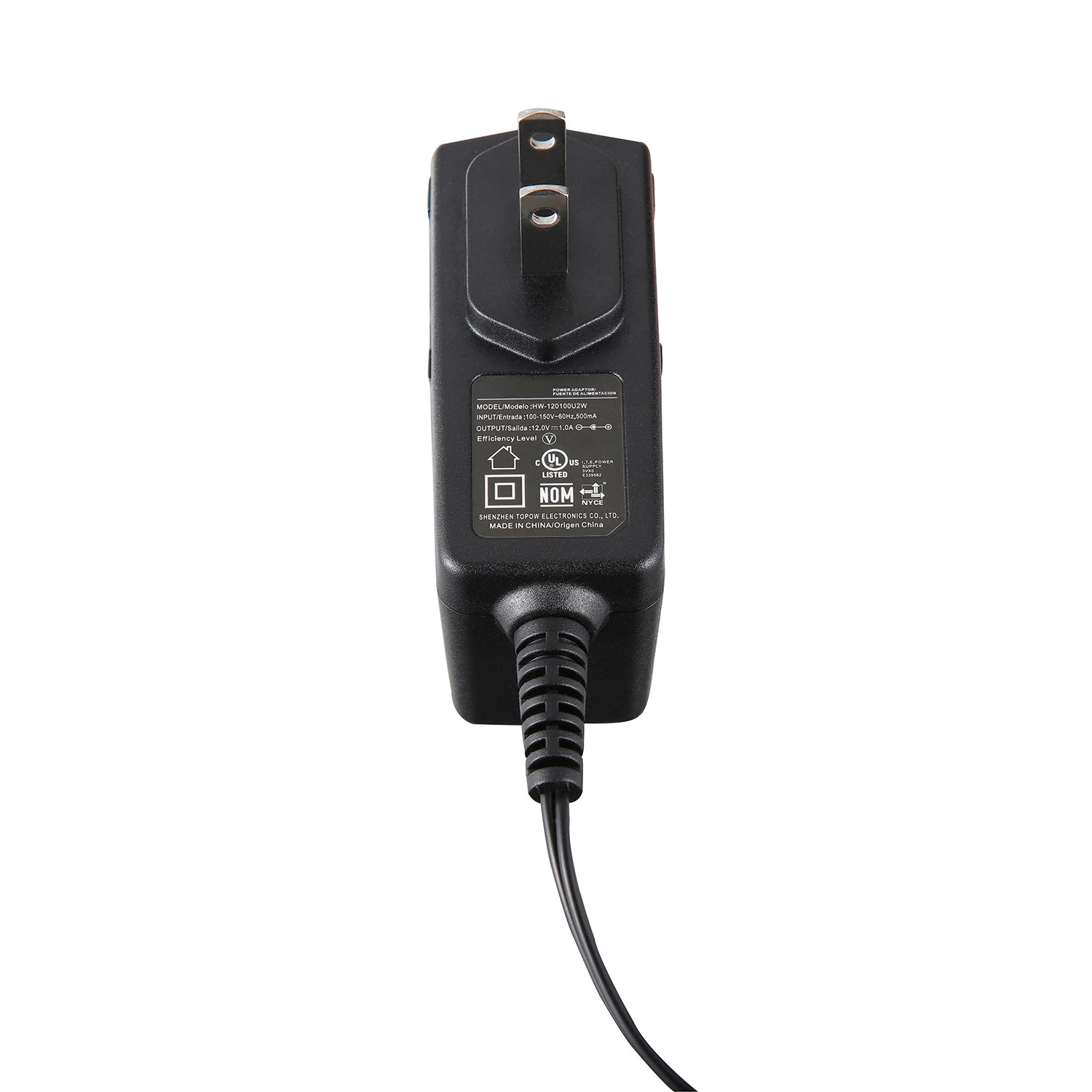
Input voltage: 100~240VAC
Input frequency: 47~63Hz
Output voltage: 12V
Output voltage accuracy: ±5%
Output current: 1.0A
Mean time between failures: at least 100,000 hours
Protection: OCP, SCP, OVP
Efficiency: >73%
Inrush current: cold start 220VAC/30A
Working temperature: -10~+45°C
Safety certification: UL
Packing: 0.092kg/80pcs/9kg
Warranty period: 2 years
General
The specification defines the performance characteristics of a 12 W, SINGLEOutputlevelswitching power supply for IT. The power supply has designed highly reliable and meet international safety and radiation requirements.
1.0Input Characteristics
1.1 Input voltage range and frequency
Nominal Voltages | Voltage Variation Range | Nominal Frequency | Frequency Variation Range |
127VAC | 85-166VAC | 60Hz | 54-66Hz |
Rated voltage: 127VAC
Voltage variation range: 85-166VAC
Rated frequency: 60Hz
Frequency range: 54-66Hz
1.2Input Current
0.5A max | At AC low line input and DC output full load |
At low line AC and full load, the maximum input current is 0.5A
1.3Input protection
2A Fuse | The power supply shall be protected against power line surges and any abnormal condition. |
When the AC input voltage has surges and abnormal conditions, the 2A fuse will protect the power supply
1.4Input surge current
30A max | At power supply cold start, ambient temperature 25℃@127Vac |
At an ambient temperature of 25°C, when the input is 127Vac cold state, the maximum inrush current is 30A
1.5Efficiency
1.5.1 min.At nominal input voltage,maximum load and measured at end of DC cable
Under the rated input voltage and full load, the efficiency of the DC terminal is minimum
1.5.2 Active mode efficiency:
More than 77.9 %min of average efficiency of 25%,50%,75% and 100% load tested at 115Vac.(Warm up after 30 minutes)
115Vac input, the average efficiency under test 25%, 50%, 75%, 100% load conditions is at least 77.9%
Meet Energy Star level Ⅴ
1.6No Load Power consumption
0.3Wrms max | At AC nominal input@output no load |
In the case of rated input AC and output no-load, the maximum no-load loss is 0.3W
Meet Energy Star level Ⅴ
1.7Hold up time
10ms min | At AC nominal input@ output full load |
(1 half cycle) |
Under the condition of rated input AC and output full load, the minimum holding time is 10ms.
2.0Output Characteristics
2.1Turn on delay
3Smax | At AC low line input@output full load |
In the case of AC low voltage input and output full load, the boot delay time is up to 3S
*Test on delay is measured from 0 voltage output to the main output regulation.
2.2DC output regulation
Voltage(V) | Loading(A) | ToleranceRange Total Regulation | Adjustable voltage | Range(V) | |
Max | Min | ||||
+12.0 | 1A | 0A | ±5% | None | 11.4~12.6 |
*Total regulation involved line regulation load regulation cross regulation---etc.
*Line regulation is measured from 85vac to 166vac
*Load regulation is measured all output from min load to max load at
127vac nominal AC input voltage
*At the all input voltage, a dynamic load state is the instantaneous current 1.4 A last 100mS, then the current change to 1A last 4S,the all state last 45S every time, the current rate 1 A/us, refer to the below waveform
*The total adjustment rate relates to the cross adjustment rate of linearity and load
*The test condition of linear adjustment rate is 85Vac to 166Vac
*The test condition of the load regulation rate is the change from the minimum load to the maximum load under the condition of 127Vac input.
*Full input voltage range, ringing transient load 1.4A, 1 A after stop ringing, total time of peak load is 45S each time, 1.4A each time is about 100mS, current change rate 1A/us, please refer to the waveform below
")
2.3Ripple/noise
Voltage(V) | Ripple/Noise(pk-pk)(mV) |
+12.0 | 120mV |
*The ripple is measured from peak to peak with band width limit of 20MHZ
(By passed at the end of connector with 10uF electrolytic and 0.1uF ceramic diskcapacitor under DC output full Load, AC nominal input 25℃ambient temperature).
*Ripple is obtained by measuring the peak-to-peak value using an oscilloscope bandwidth of 20MHz
(Test conditions: at full DC output, rated AC input, and an ambient temperature of 25°C, a 10uF electrolytic capacitor and a 0.1uF ceramic capacitor are connected in parallel at the output end)
3.0 Protection
3.1 Short protection / Over current protection
The power supply will self-protect any output to ground, And auto recovery when
abnormal circuit faults remove.
The power supply can automatically resume normal operation when the short circuit is removed
*An output short circuit is defined as any output impedance of less than 0.1 ohms.
*When the effective value of output impedance is less than 0.1 ohm, it is defined as output short circuit
Voltage(V) | OCP Current(A) | Power in(W) | OCP method | ||
latch off | Current limit | Fold back | |||
+12.0 | 1.4-2.0 | <4 | |||
3.2Over voltage protection
Voltage(V) | OVP range | OVP Method | ||
Latch off | Auto recovery | Voltage limit | ||
+12.0 | 16V max | |||
Test methods: Short FB Pin to GND
3.3 Over Temperature Protection
No deformation and no discoloration on case and will be shut down. That will be return
To normal state by ac reset, reset≤2 minutes.
When the power supply is turned off, the shell is not damaged or stained. When the AC input is restored, the shell can be restored to a normal state, and the recovery time is less than 2 minutes.
4.0 Leakage current:
Leakage current 0.25 mA max@240VAC
When the input voltage is 240Vac, the maximum leakage current is 0.25mA
5.0 Safety meet of IEC60950-1
5.1 EMI/EMS standards EMI/EMS STANDARDS
5.1.1 EMI CE (150K-30MHZ) and RE (30M-1GHZ) meet EN55022 standard
5.1.2 EN61000-4-2 ESD immunity requirements
5.1.2.1 Air discharge +/- 15KV (B)
5.1.2.2 Contact discharge +/- 8KV (B)
5.2 EN61000-4-3 radiated disturbance field strength RS
10V/m (r.m.s) 80-1000Mz 80%AM (1KHz) sine-wave (A)
5.3 EN61000-4-4 Electrical Fast Transient Burst BURST
5.3.1 AC input port AC-input coupling 2KV (A)
5.3.2 AC input port AC-input coupling 2KV (B)
5.4 EN61000-4-5 Surge immunity test SCR
5.4.1 Common mode/differential mode +/- 6KV / +/-6KV
5.5 Induced radio frequency fields conducted disturbances immunity test
10V 0.15-80 MHz 80%AM (1KHz) (A)
6.0HI-POT AND Insulation Resistance
HI-POT: Primary to secondary 3000Vac/10mA/60S.
IR: primary to secondary ≥100M ohm at 500Vdc
7.0Environment
TEMPERATURE AND HUMIDITY
OPERATING TEMPERATURE -5 DEGREES C TO 45 DEGREES C.
OPERATING HUMIDITY 5% TO 95% RH.(RELATIVE HUMIDITY).
STORAGE TEMPERATURE -40 DEGREES C TO 70 DEGREES C.
STORAGE HUMIDITY 5% TO 95% RH. (RELATIVE HUMIDITY).
Working temperature: -5℃-45℃
Working humidity: 5%-95% (relative humidity)
Storage temperature: -40℃-70℃
Storage humidity: 5%-95% (relative humidity)
8.0Vibration
SWEEP AND RESONANCE SEARCH
FREQUENCY DURATION AXIS AMPLITUDE
10~55Hz 30 MINUTES X,Y,Z 1G
9.0M.T.B.F
Shall be 60000power on hours on greater under 25 degrees C of ambient temperatureMTBF
Underevaluated under.
*M.T.B.F. 60000 hours will be affected if the product won’t be used for a long time.
10.0 Label specification: As Attachment
11.0 Mechanical: As Attachment
12.0 Appearance: As Attachment
13.0 Package: As Attachment
14.0 SCH&PCB: As Attachment
15.0 Bill of materials: As Attachment


About

Product
Process
News
Recruitment

 中文
中文 Online consultation
 Online map
 中
中