
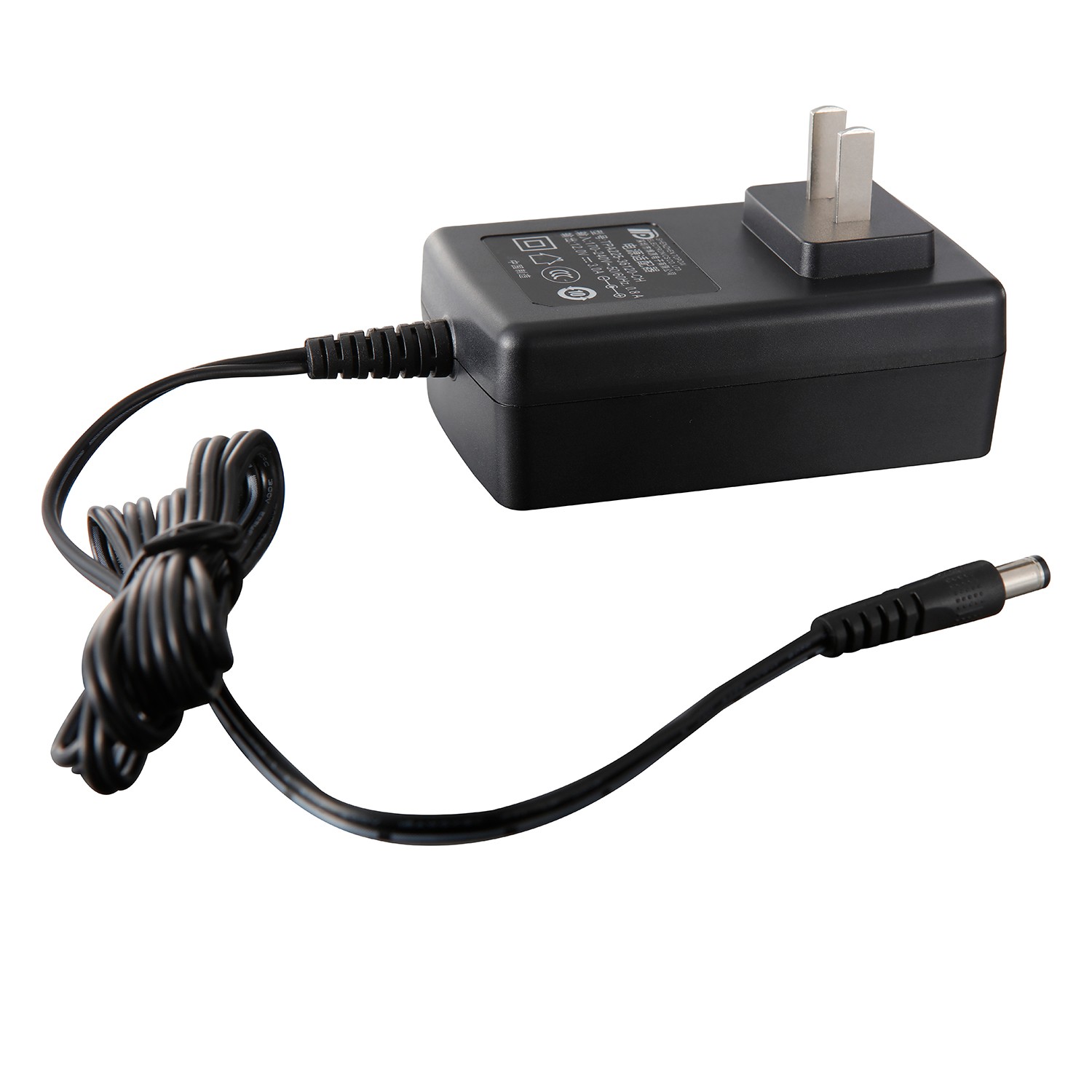
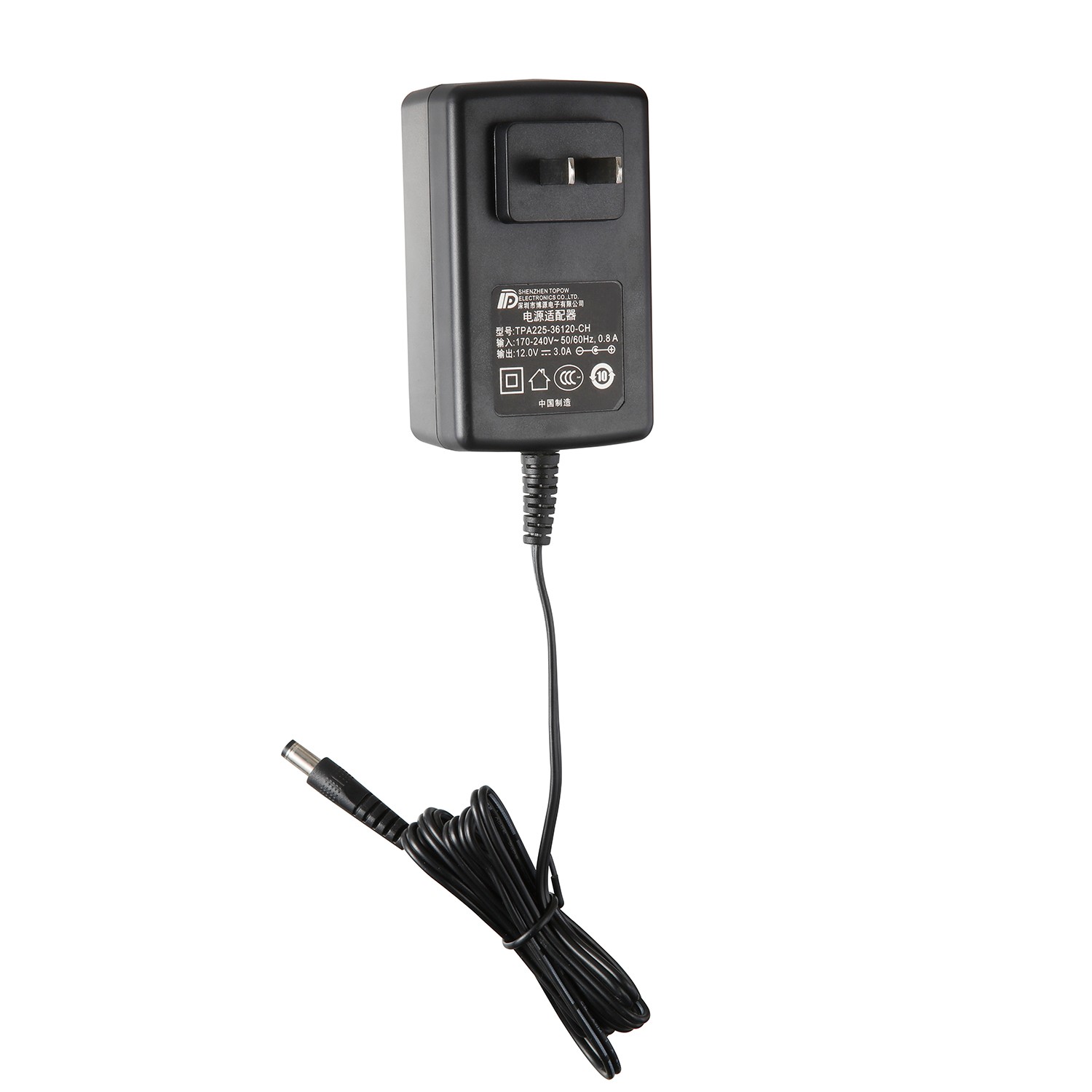
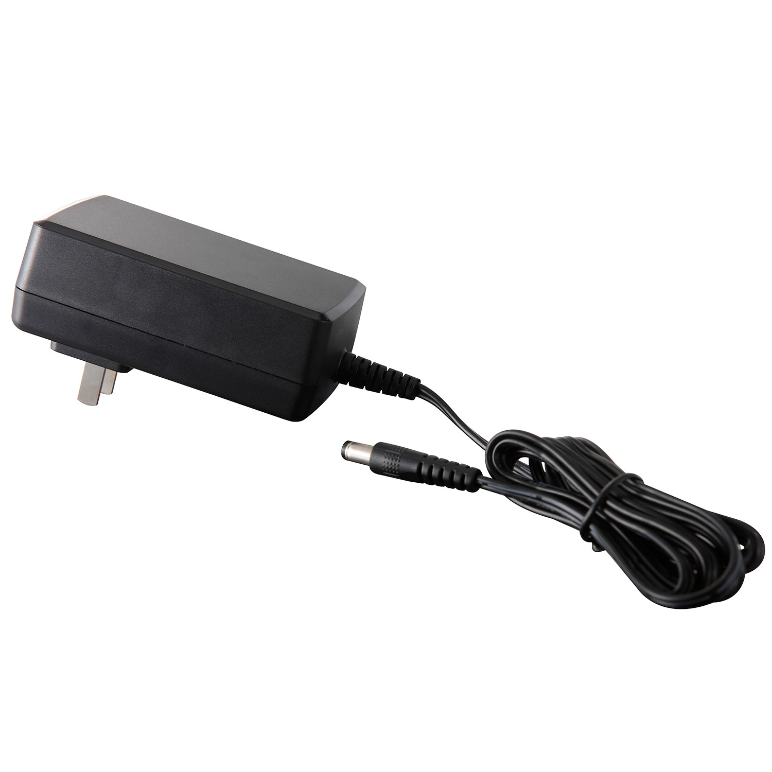
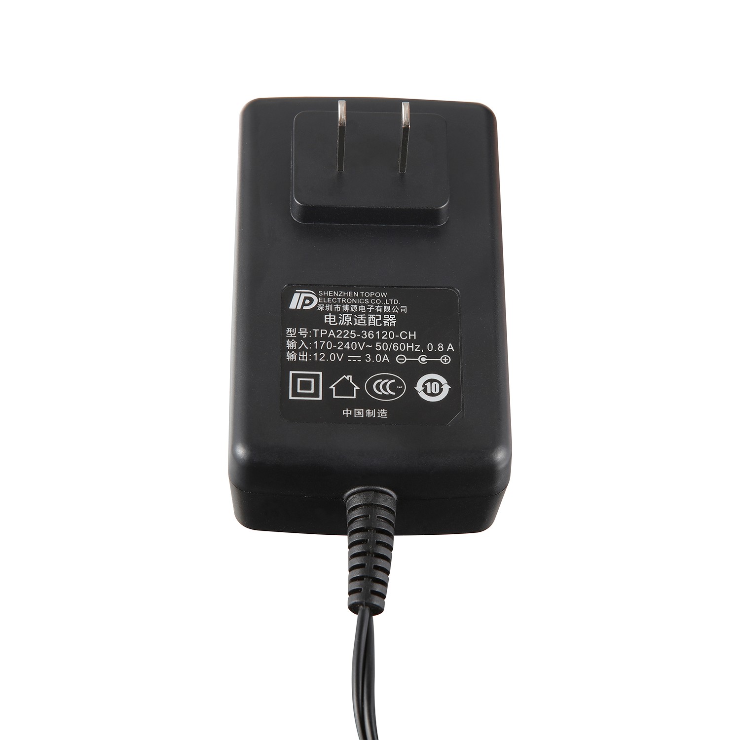
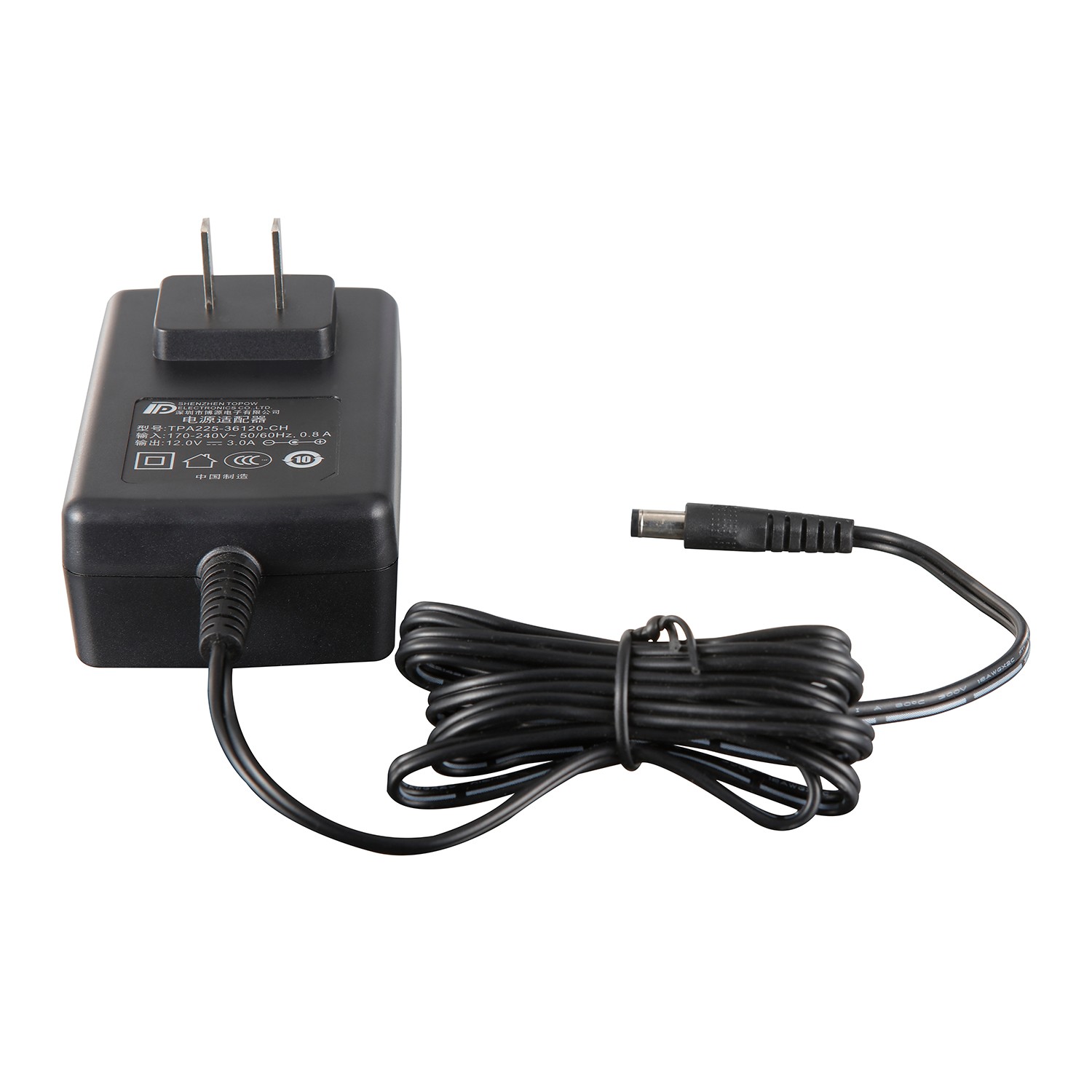
Color: Black
Plug Type: Wall-mounted horizontal, CN version
Output Power: 36W
Input Voltage: 150~264V
Input Frequency: 47~63Hz
Output Voltage: 12V
Output Voltage Accuracy: 5%
Output Current: 3A
MTBF: At least 100,000 hours
Protection: OCP,OVP
Efficiency: 85%
Inrush Current: Cold start 60A/220VAC
Working Temperature: -5~+45°C
Safety Certification: CCC
Packing: 0.19kg/60pcs/12kg
Warranty Period: 2 Years
1 Overview
This specification specifies the detailed specifications of the 36W (12V/3A) custom power adapter designed and developed by our company.
2 function description
The power adapter can complete the conversion from AC to DC, 150Vac~264Vac input can work normally, rated 12V output, Chinese plug. The power supply has input over-current protection, output short-circuit protection, output current-limiting protection and other functions, and the efficiency meets the ErP V energy efficiency requirements.
3 Power supply environmental specifications
Table 1 Environmental parameter table
Project | Unit | Minimum | Typical value | Max | Remarks |
Operating temperature | ℃ | -5 | 25 | 45 | |
Storage temperature | ℃ | -40 | 25 | 70 | |
Relative humidity | % | 5 | / | 95 | No condensation |
Altitude | m | 0 | 0 | 5000 |
4 Electrical characteristics
4.1 Input characteristics
4.1.1 Basic input characteristics
Table 2 Input the basic characteristics table
Project | Unit | Minimum | Typical value | Max | Remarks |
Rated input range | Vac | 170 | 220 | 240 | |
AC input voltage range | Vac | 150 | 220 | 264 | The maximum input of 282Vac will not be damaged for a long time, and it will be checked and accepted within 4 hours (can not work); input undervoltage will not be damaged |
AC input voltage frequency | Hz | 47 | 50/60 | 63 | |
Input Current | A | / | / | / | Low voltage full load |
No-load power consumption | W | / | / | 0.3 | Requirements: Rated input at room temperature |
AC input system | / | / | Single phase input | / | Single phase input |
Input impulse current | A | 60 | 1. Under 220VAC conditions, cold start, meeting standard requirements: ETSI300132-3 2. Cooperate with 10A, B trip curve MCB, simulate adapter plug-in or power-off and call-on scenarios, the MCB cannot be tripped |
")
ETSI300132-3 impulse current standard diagram
4.1.2 Input protection features
Table 3 Input protection characteristics
Project | Unit | Minimum | Typical value | Max | Remarks |
Input overcurrent protection | / | / | / | / | 1. There is a fuse at the AC input, two-level overcurrent protection 2. Over current protection, after the adapter's internal short circuit/overload, it needs to be safely isolated from the power grid; 3. Pressure-sensitive protection. After pressure-sensitive lightning strikes are damaged, it is necessary to ensure that the main circuit of the adapter input is disconnected; 4. The selection of overcurrent protection devices should consider that there should be no risk of melting shell under abnormal conditions; |
Input undervoltage protection | / | / | / | / | Not damaged |
4.2 Output characteristics
4.2.1 Basic output characteristics
Table 4 Output basic characteristics table
Project | Unit | Minimum | Typical | Max | Remarks |
Output Power | W | / | 36 | / | Full input voltage range; |
Output voltage range | Vdc | 11.4 | 12 | 12.6 | Full voltage input range, full load output |
Output efficiency | % | 84.8% | / | / | Meet ErP V energy efficiency requirements (rated input at room temperature, the average value of the efficiency measured under 25%, 50%, 75%, and 100% load respectively) |
Stabilization accuracy | % | / | / | ±5 | Full voltage input range, full load output |
Source adjustment rate | % | / | / | ±2 | Rated current output, full voltage range change |
Noise + ripple (peak-to-peak value) | mV | / | / | 120 | It is carried out within the rated input voltage and load range, and one 0.1uF ceramic or gold film capacitor and one 10uF electrolytic capacitor are connected to the output during the test. The bandwidth of the oscilloscope is 20MHz |
Dynamic response recovery time | us | / | / | 200 | @25%~50%~25% or 50%~75%~50% load change, current change rate 0.1A/us, cycle 4ms |
Switch overshoot | % | / | / | ±5 | |
Dynamic response overshoot | % | / | / | ±5 | @25%~50%~25% or 50%~75%~50% load change, current change rate 0.1A/us, cycle 4ms |
Output rise time | ms | / | / | 200 | The output voltage rises from 10% to 90%, rated load |
Power-on output delay | s | / | / | 3 | |
Hold time | s | / | / | / | no request |
Temperature Coefficient | %/℃ | / | / | ±0.02 | Rated output voltage and output current, full range of operating temperature |
Capacitive load | uF | 3000 | When the output is connected to a 3000uF capacitor with a full load, the output rises monotonically when the output starts |
4.2.2 Output protection features
Table 5 Output protection characteristics table
Project | Unit | Minimum | Typical value | Max | Remarks |
Output current limit protection point | A | 3.5 | / | 5 | Hiccup protection mode, long-term over-current and short-circuit, no damage; over-current inflection point stress does not exceed the standard. |
Output short circuit protection | / | / | / | / | Long-term short circuit, hiccup protection mode, self-recovery, no damage |
Output overvoltage protection | V | 13.5 | 16 | Hiccup protection mode, no damage | |
V | / | / | 16 | Not damaged Remarks: PSR scheme OVP does not set a lower limit. |
4.3 Other requirements
Table 6 Other requirements table
Project | Claim | Remarks |
Thermal requirements | Natural heat dissipation | |
Odor requirements | No peculiar smell and unhealthy smell | |
Device requirements | Refer to the general specifications of customer devices | |
Process requirements | 1. The automation rate reaches 76%, and the challenge is 80%; 2. PCBA is required to be 100% free from cutting feet. | Automation rate = (SMT device + AI device) quantity / quantity of all components |
Failure isolation | The internal output is overvoltage, the module can not damage the power receiving equipment. Reliable isolation must be achieved after the power module fails. | Power failure cannot damage the power receiving equipment |
Environmental requirements | Need to meet RoHS 2.0 EU 2015/863, prohibit the use of 4 phthalate substances (DEHP, BBP, DBP, DIBP) (for all electrical and electronic equipment) | Meet RoHS 2.0 EU 2015/863 and Reach directive |
special requirements | Involving voice. |
5 Safety requirements
5.1 Basic requirements
The power supply must obtain safety certification in the form of an independent product and meet the requirements of its corresponding safety standards.
5.2 Safety certification requirements
Expected shipping area | AC plug form | Safety certification requirements |
China |
| CCC |
Meet the GB4943.1 standard.
5.3 Safety standards
Table 7 List of safety standards
Safety standard | Safety standard content |
GB 4943-2001 | Safety of Information Technology Equipment (Including Electrical Busi ness Equipment) (standard for China, equivalent to IEC 60950) |
5.4 Key items of safety test
Table 8 Safety test requirements
Test items | Safety requirements |
Altitude insulation and distance | In considering the specifications above 2000m altitude, it is necessary to consider the correction of insulation parameters such as electrical clearance and creepage distance at high altitude. (The altitude needs to meet 5000m) |
Secondary circuit | All secondary circuits must meet the requirements of the safety special ground voltage circuit (SELV). |
Limited Power Supply Requirements (LPS) | Must meet the requirements of UL/IEC/EN60950-1 section 2.5 and UL/IEC/EN62368-1 section Q.1. |
Insulation resistance test | Japan no longer requires insulation resistance testing. Although the insulation resistance test is not required in Singapore's national differences, the test result is still required when the final product enters Singapore for evaluation. So the power supplier must carry out this test and include it in the CB report. |
5.5 Production line test requirements
100% withstand voltage test of the power supply during the production process
The ground continuity test is performed at the on and off positions of the input switch.
Table 9 Production line test requirements
Insulation voltage | (1) The primary to secondary should be able to withstand 50Hz, 3000VAC withstand voltage for 1 minute, leakage current ≤ 10mA, no breakdown or arcing; | The equivalent DC voltage can be used for testing. |
Insulation resistance | Normal atmospheric pressure, relative humidity <90%, under non-condensing conditions, when the test voltage is 500VDC, the insulation resistance between the primary and the secondary is ≥100MW | |
Leakage current | <0.25mA (264VAC, 60Hz input) |
5.6 Other
Meet the requirements of TT, TN, and IT power distribution systems.
The material of the adapter housing is required to reach the V-0 level (UL94). Under normal working conditions, the housing temperature is required to be less than 75 degrees, and under abnormal conditions ((overcurrent, overvoltage and other two-zone environments)) the housing temperature is required to be less than 95 degrees.
The altitude must meet the 5000m requirement.
6 EMC requirements
Table 10 EMC requirement table
Project | Index requirements | standard |
Conducted interference | Input port: CLASS B, with a margin of more than 6dB for ungrounded monomers, and a margin of more than 4DB for bulk monomers. | EN55032:2015 |
Radiation interference | CLASS B, ungrounded monomers have a margin of 6dB or more, and bulk monomers have a margin of 4DB or more. | EN55032:2015 |
SURGE | AC port: Differential mode: ±4kV impedance 2ohm Common mode: ±6Kv, impedance 2ohm Waveform 1.2/50us, criterion B; reference standard ITU-T K.21 Remarks: 1. When testing, the output terminal must be tested for grounding and ungrounding 2. It is required to meet the error requirement of +/-10% 3. The output needs to meet the requirements without load and with load. Criterion B description: During the interference application process of the EUT and after the interference application is completed, the voltage change of the DC output port is within the accuracy range declared in its specification, and the instantaneous change within 1ms is ignored, and it is not allowed to cooperate with the whole machine. A power-down reset of the whole machine occurs. After the surge limit test fails, the shell shall not burst. | 参考标准ITU-T K.21 |
EFT | Criterion B±2kV | IEC61000-4-4
|
DIP | AC port DIP requirements IEC61000-4-11 Drop to 0, duration 10ms, drop at each phase of 0°, 45°, 90°, 135°, 180°, 225°, 270°, 315°, meeting criterion B; When it drops to 0, the duration is 20ms, and all phases of 0°, 45°, 90°, 135°, 180°, 225°, 270°, 315° meet criterion B; Drop to 70% UT, duration 500ms, and all phases at 0°, 45°, 90°, 135°, 180°, 225°, 270°, 315° meet criterion B; Drop to 0%UT, duration 5000ms, all phases of 0°, 45°, 90°, 135°, 180°, 225°, 270°, 315° meet criterion C | IEC61000-4-11 |
ESD | Criterion B Contact discharge: ±8kV Air discharge: ±15kV | IEC61000-4-2
|
CS | LEVEL 3; Criterion A; 10V | IEC61000-4-6 (You need to use an oscilloscope to monitor the output voltage. There can be glitches, but there can be no instantaneous interruption and long-term interference. The waveform needs to be reflected in the test report) |
RS | Level 3; Criterion A; 10V/m field strength | IEC61000-4-3 (You need to use an oscilloscope to monitor the output voltage. There can be glitches, but there can be no instantaneous interruption and long-term interference. The waveform needs to be reflected in the test report) |
Voltage fluctuation and flicker | Voltage fluctuations and flicker limits for class A products | IEC61000-3- 3 |
Current harmonic emission | Harmonic current limit for class A products | IEC61000-3- 2 |
Note 1: The power module needs to meet the ETSI300 132 standard.
Performance criterion:
Criterion A-Normal performance within the scope of technical requirements;
Criterion B-Some functions can be temporarily deteriorated or lost, and can be self-recovered, but the output voltage must be kept within the normal range during the test;
Criterion C: Automatic reset with short-term functional interruption is allowed, and long-term functional interruption or manual reset is not allowed;
Criterion R: No damage to any device other than the protection device is allowed, and the test piece can recover its performance after replacing the damaged protection device.
7 Mechanical structure requirements
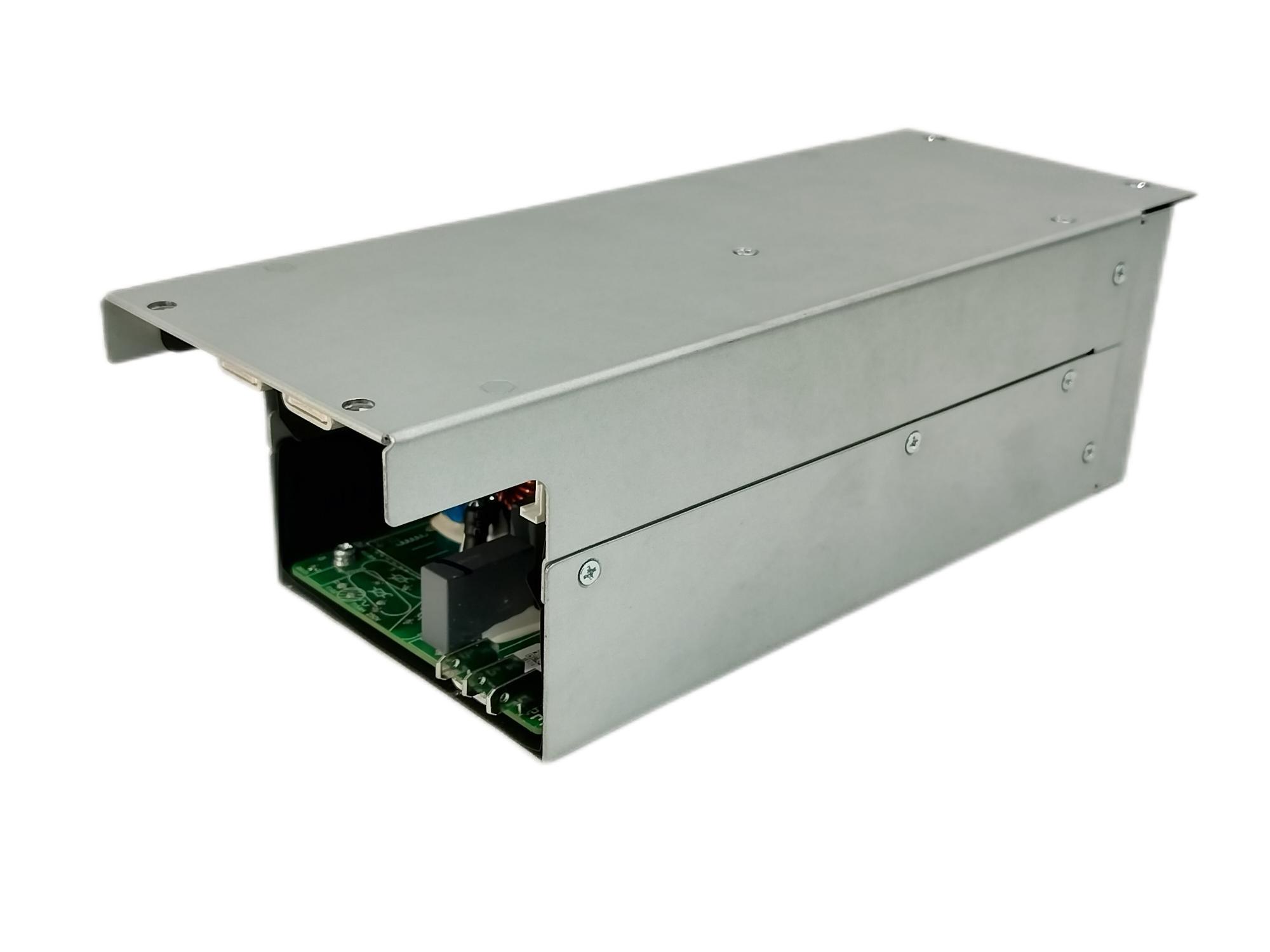
7.1 Shape, interface terminal
See attachment 1
7.2 Labels, nameplates
See attachment 2
7.3 Appearance
See Annex 3
8 Environmental test requirements
8.1 Routine environmental test
Table 11 Routine environmental experiment requirements table
Serial number | Pilot projects | Reference standards/test parameters | Preliminary stage | Positive stage | Small batch stage | Remarks |
1 | (Low Temperature Work) | Use environment minimum temperature test Test duration: 24h | √ | √ | Mandatory (increased voltage bias test) | |
2 | (High Temperatrue Work) | Use environment maximum temperature test Test duration: 24h | √ | √ | Mandatory (increased voltage bias test) | |
3 | (Low Temperature Storage) | -40℃,24h | √ | Must do | ||
4 | (High Temperature Storage) | 70℃,24h | √ | Must do | ||
5 | (Humidity Cross) | Indoor: 25~40℃, 95% | √ | Must do | ||
6 | (Temperatrue Cycling) | Indoor: -10℃~45℃
| √ | Must do | ||
7 | (Thermal Shock) | -40℃~70℃ | √ | √ | Refers to modules only Choose to do | |
8 | (Vibration Test) | 5-9Hz, 3.5mm; 9-200Hz: 1g; 3 axes, 5 sweeps per axis. | √ | Must do | ||
9 |
| Half-sine shock spectrum, 11ms/5g (equipment greater than 100kg) 6 directions, 3 shocks in each direction | √ | Must do | ||
10 | (Drop Test) | 1 Corner, 3 Edges, 6 Surfaces each once. Drop on the cement plane, Height: 100cm, | √ | Must do | ||
11 | Temperature derating curve | √ | not involving | |||
12 | Output DC plug insertion force test | Test the insertion force with the socket of the whole machine: 30N MAX Pull-out force: 5N~20N; for details, please refer to the following "ONT Power Adapter DC Plug Insertion-Pull Force Test Operation Guide" | √ | |||
13 | Tensile test | 5kgf;1min | √ | Must do | ||
14 |
| Angle: ±90°; Frequency: Wire 60 times (single pendulum)/min, DC connector and SR root wire 60 times (back and forth)/min | √ | Must do | ||
15 |
| Lift 5kg, hold for 1min, and test the entire adapter (including plugs of wires and accessories) | √ | Must do | ||
16 | Output DC plug insertion force test | Test the insertion force with the socket of the whole machine: 30N MAX pull-out force: 5N~20N | √ | Must do | ||
17 | Low temperature bending test of output wire | Immediately after storing for 24 hours at a low temperature of -30 degrees, bend the SR root wire at 90 degrees for 5 times, and the output line and SR cannot be broken | √ | Must do | ||
18 | Corrosive gas (salt spray) test | After the salt spray test, the exposed metal and electroplated parts of the power supply have no corrosion or rust after the salt spray test. For details, please refer to the "Customized Power Adapter Test Guide for Outsourcing" | √ | Note: There is no requirement if it is not placed in a corrosive environment. | ||
19 | Adapter body and AC cable retention test | The holding force is required to be 10N~60N, refer to JIS C 8303 and JIS C 8306. | √ | Must do |
8.2 Packaging and transportation experiment
Table 12 Test Requirements for Packaging and Transportation
Serial number | Pilot projects | Reference standards/test parameters | Preliminary stage | Positive stage | Small batch stage | Remarks |
1 | Random vibration | Frequency Acceleration Spectral Density 5Hz: 0.01/Hz; 100Hz: 0.01/Hz; 200Hz: 0.001/Hz; Total root mean square acceleration: 1.14Grms Test axis: 3 axis. Test time: X axis 40min; Y axis 10min, Z axis: 10min | √ | Packages (mandatory for all A-type packages and mandatory for B-type packages less than 100kg) Test quantity: 3pcs Subject to shipping packaging | ||
4 | fall | Surface, corner, edge drop: Weight range Drop height 50~68kg, 46cm 40~50kg, 50cm 30~40kg, 61cm 20~30kg, 80cm 10~20kg, 100cm ≤10kg, 120cm Drop 4 corners, 3 edges and 6 faces: 4 corners: If one of the bottom corners can be judged to be the weakest, this bottom corner will be used as the falling object; if it cannot be judged, choose the corner 2-3-5. Others are: angle 3-4-5, angle 1-2-5, angle 1-2-6 3 edges: The three edges that intersect at this bottom corner. 6 surfaces: the six outer surfaces of the package; Number of drops: 2 times for each part | √ | Package | ||
6 | Static pressure test | TL = Wt × (S-1) × F ×9.8(N) Among them: TL: the applied pressure value, the unit is N; Wt: the weight of the package itself, the unit is kg; S: the number of layers allowed to be stacked, select the maximum number of stacked layers; F: the safety factor, usually we choose 5; S=3/hh——The height of the package, in m. The time of applying pressure is maintained for 2h. | √ | Mandatory for paper packaging, optional for wooden packaging |
9 Reliability requirements
9.1 MTBF requirements
Table 13 MTBF index requirements
index | Index requirements | unit | condition | Remarks |
MTBF | 10 | Ten thousand hours | 25℃, rated input, rated output load Reference standard: Telcordia SR332 | Provide reliability prediction report, which must meet the index requirements |
9.2 Power supply service life requirements
Table 14 Requirements for the service life of the power supply
evaluation items | Index requirements | Evaluation conditions | Remarks |
Life of all electrolytic capacitors | 5 years | No additional heat dissipation measures; 30°C ambient temperature; rated input; 80% output load | The temperature of the electrolytic capacitor must be the actual measured temperature, and a photo showing the test point of the capacitor temperature must be attached to the report. |
3 years | No additional heat dissipation measures; 30°C ambient temperature; rated input; maximum output load |
10 packs
See Annex 4
11 Schematic and circuit diagram
See Annex 5
12 Bill of Materials
See Annex 6


About

Product
Process
News
Recruitment

 中文
中文 Online consultation
 Online map
 中
中


")