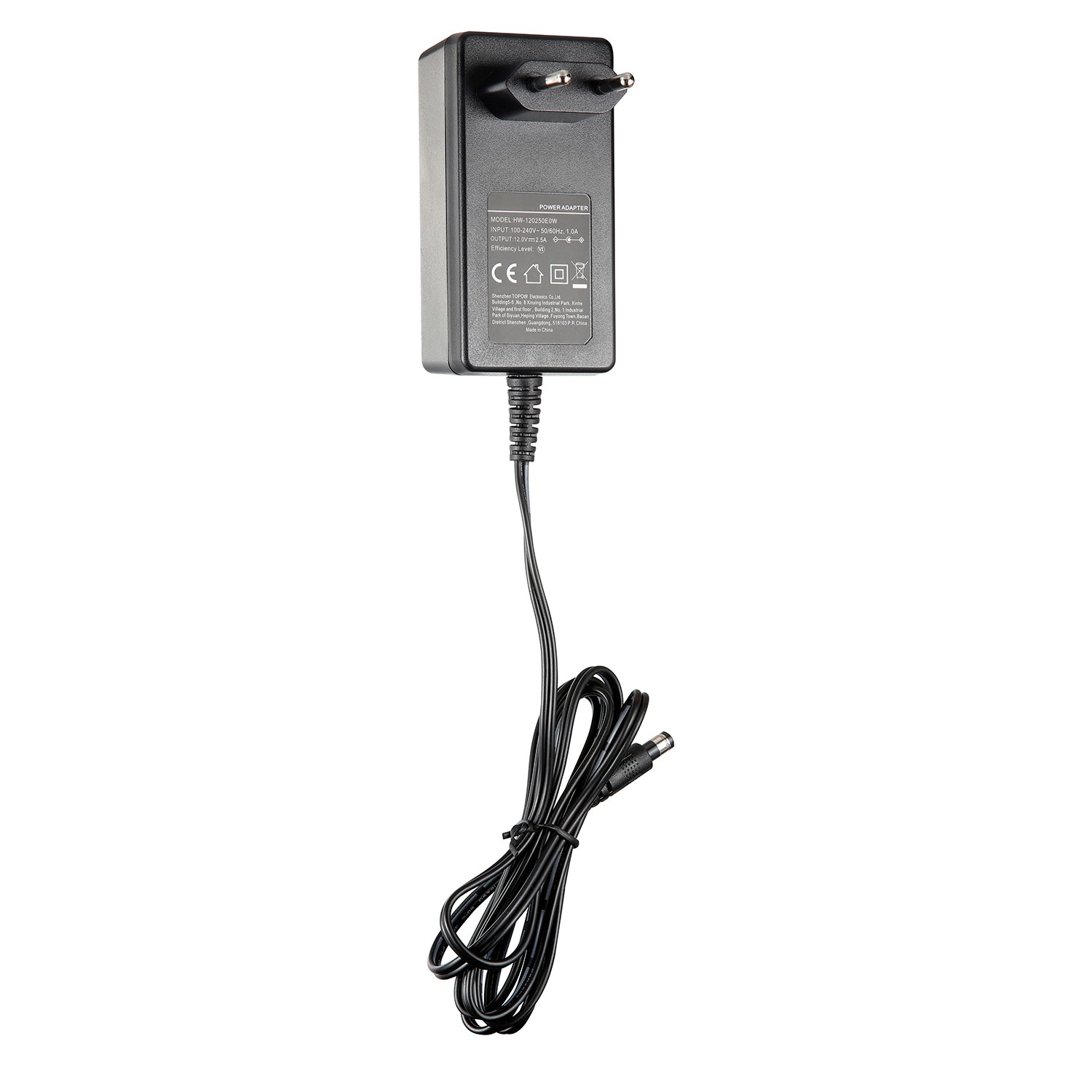
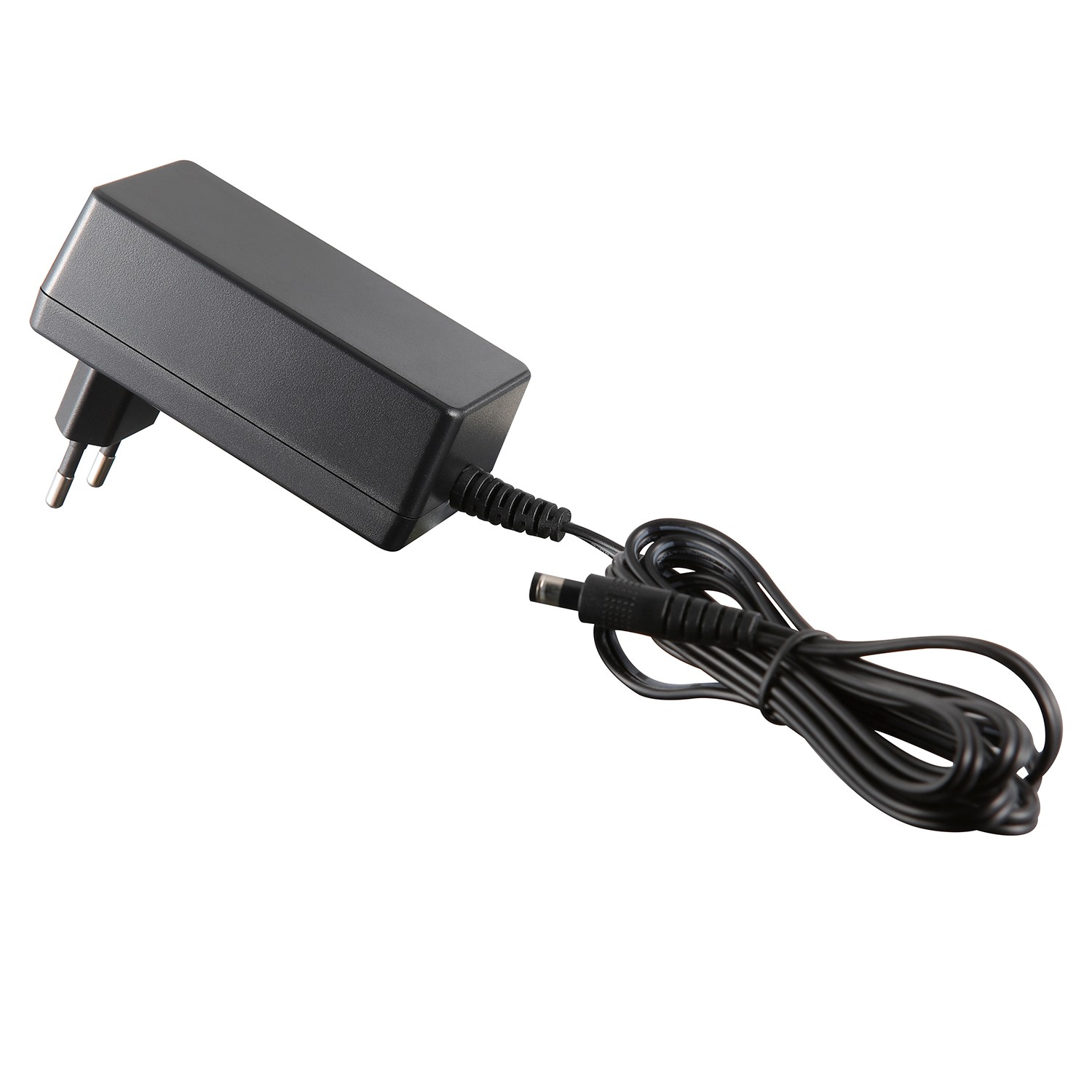
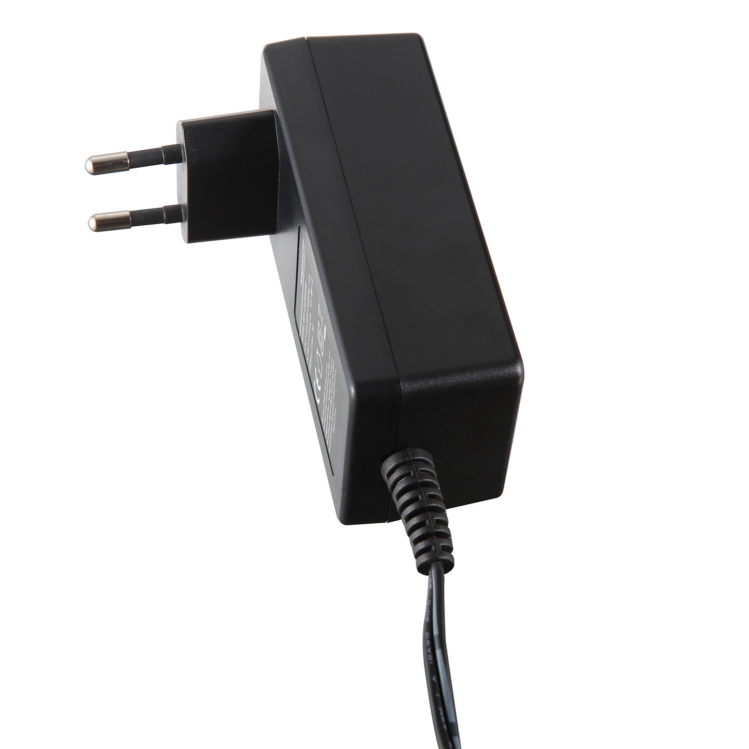
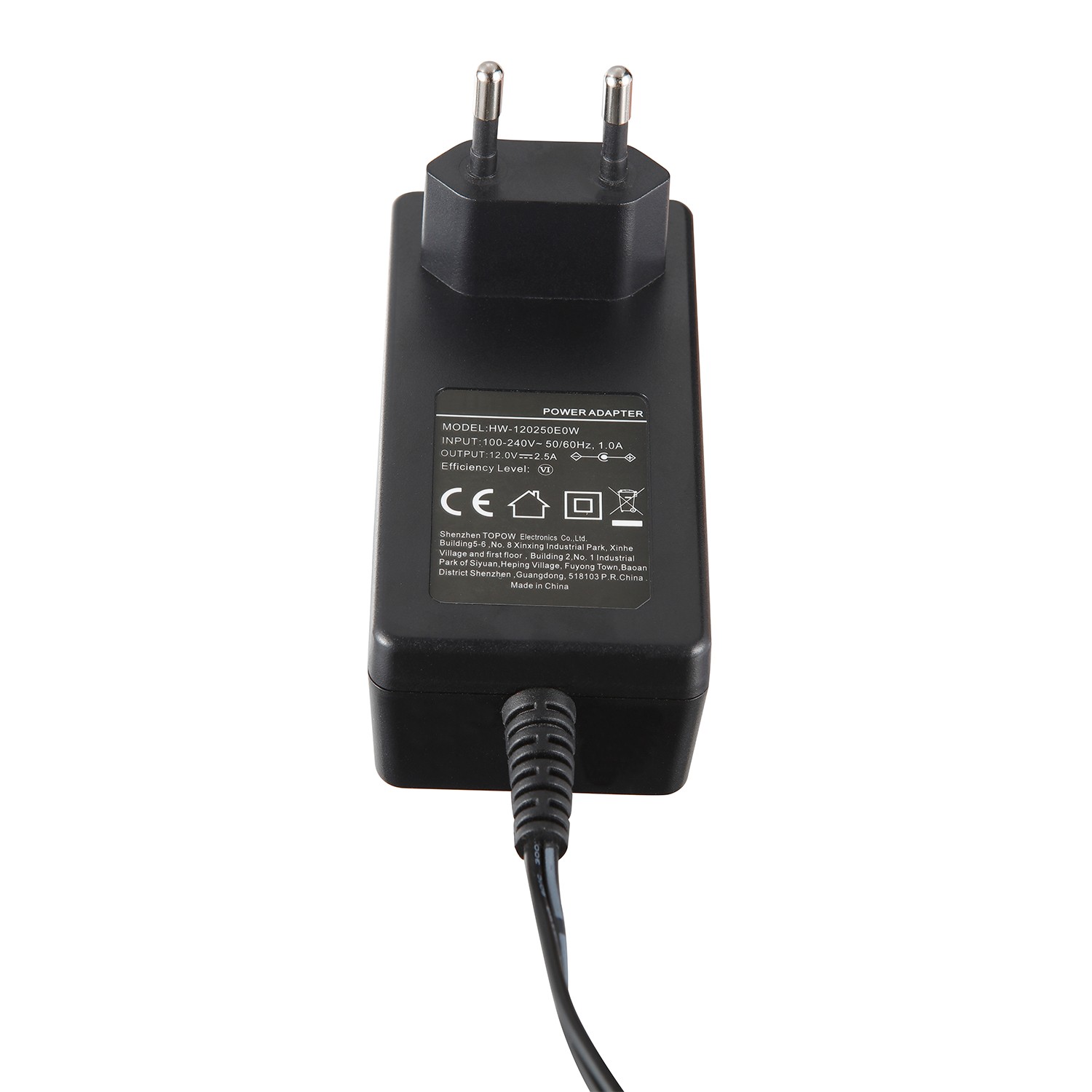
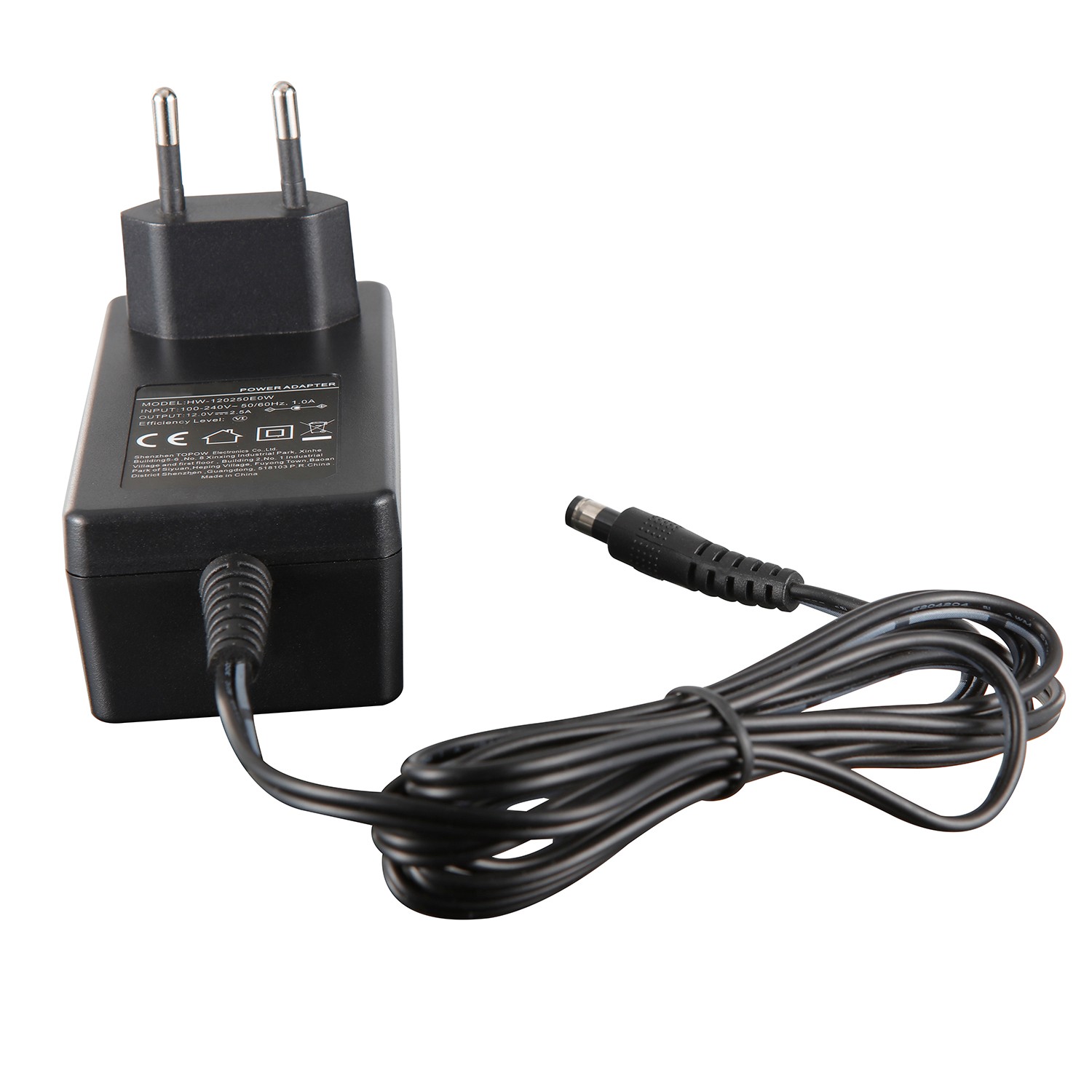
Product

>
<

30W European standard

TPA243-30120-EU

Color: Black

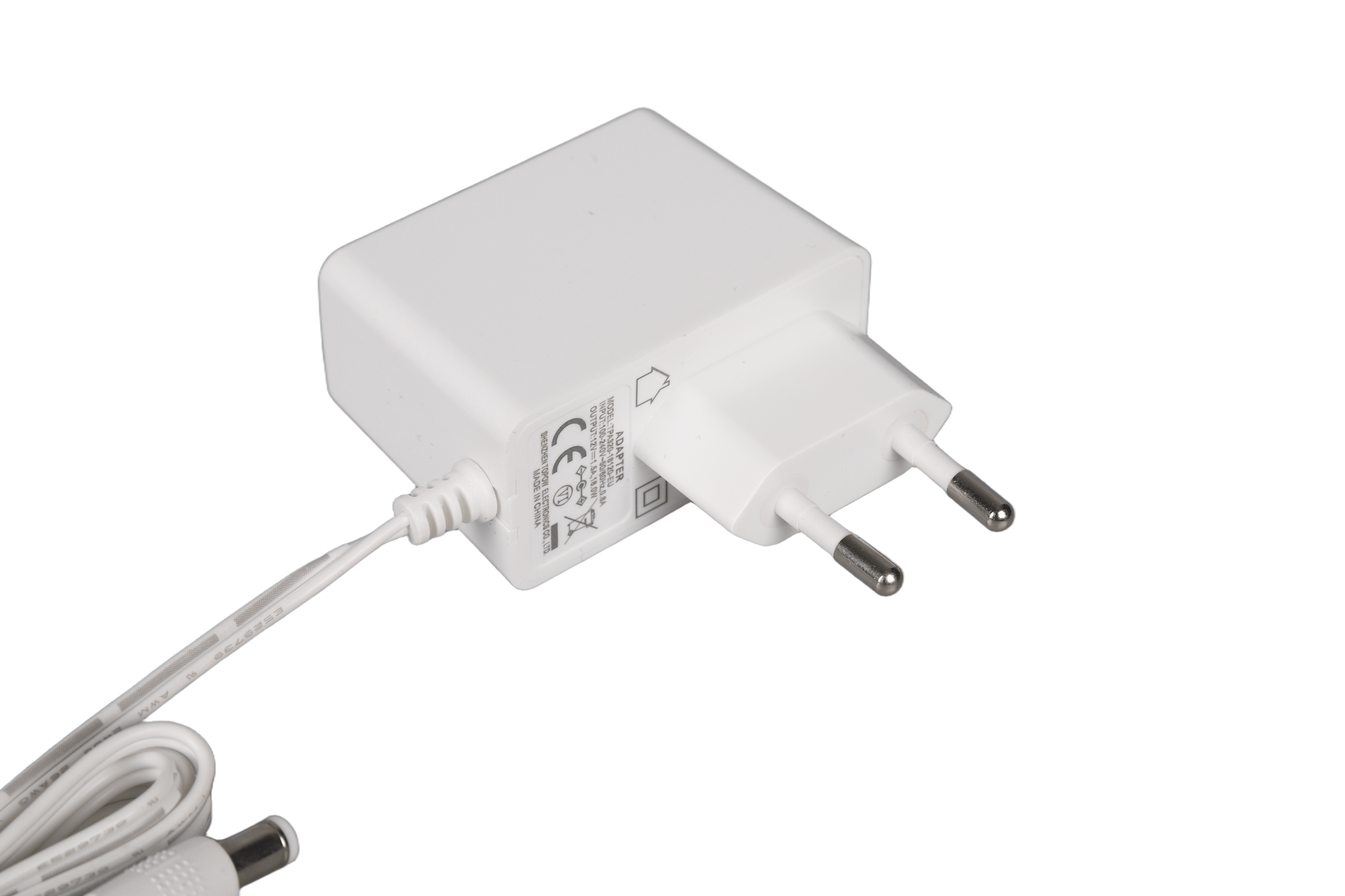
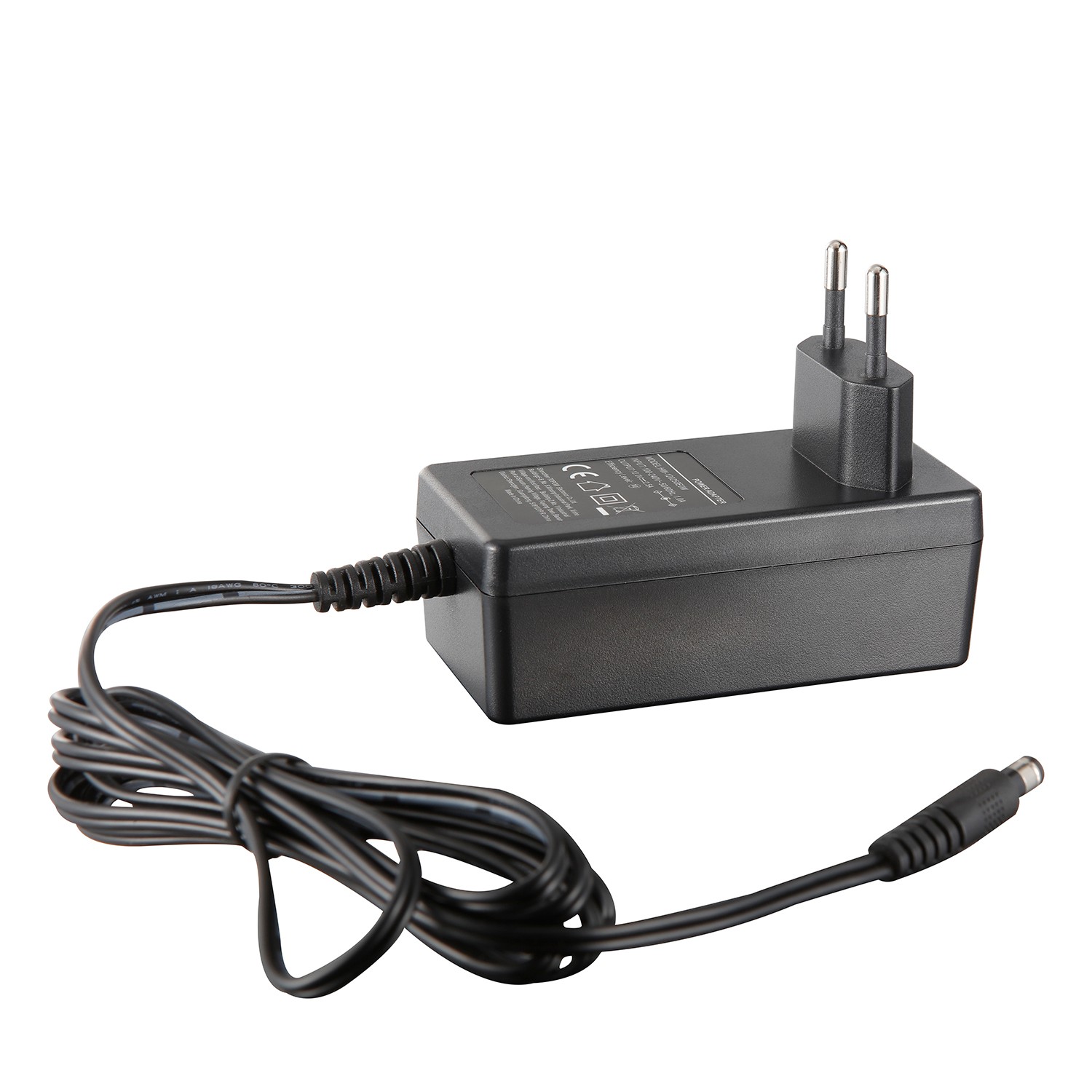
Plug Type: Wall-mounted horizontal, European standard

Output Power: 30W

Input Voltage: 90~264VAC

Input Frequency: 47~63Hz
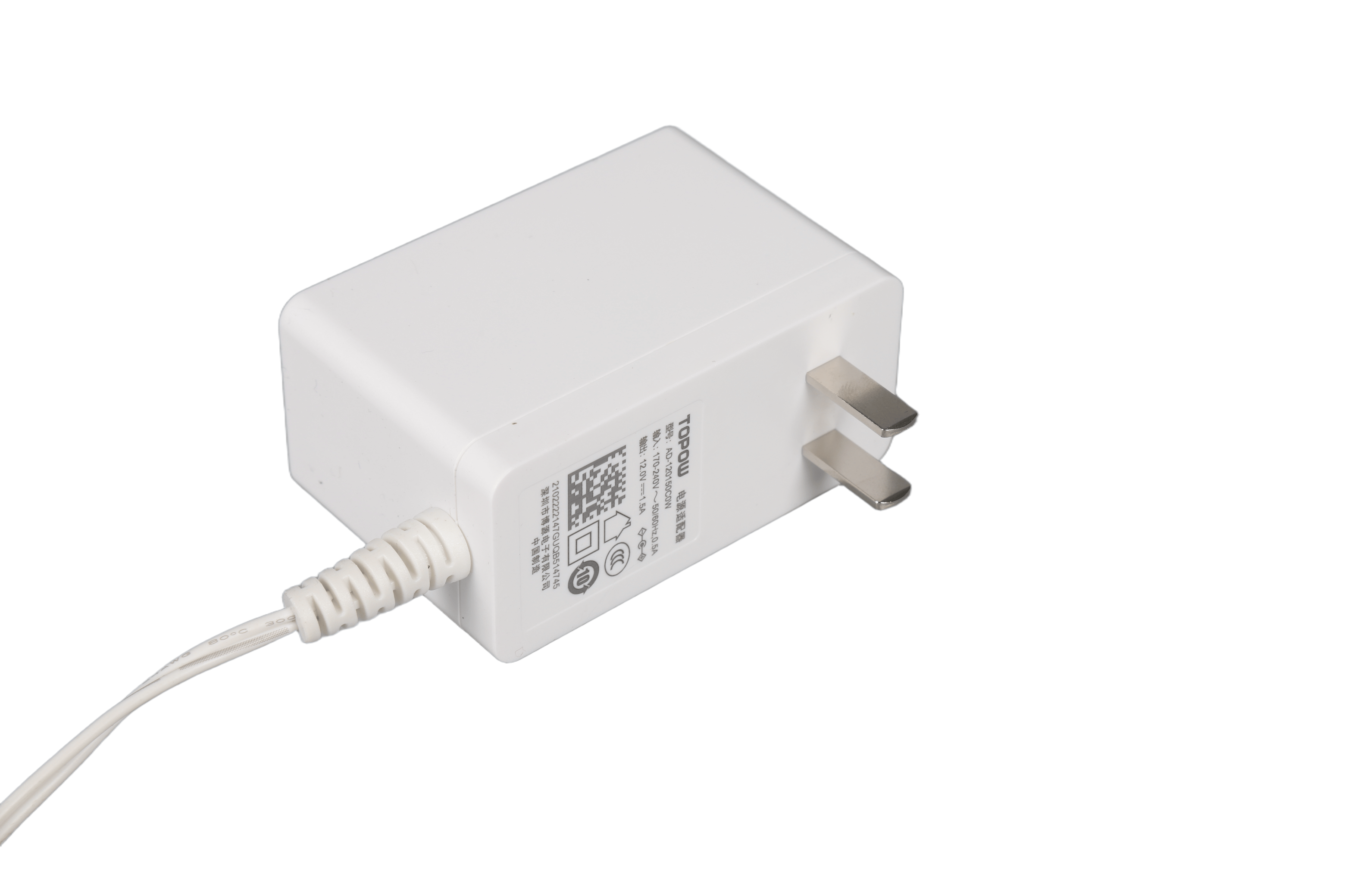
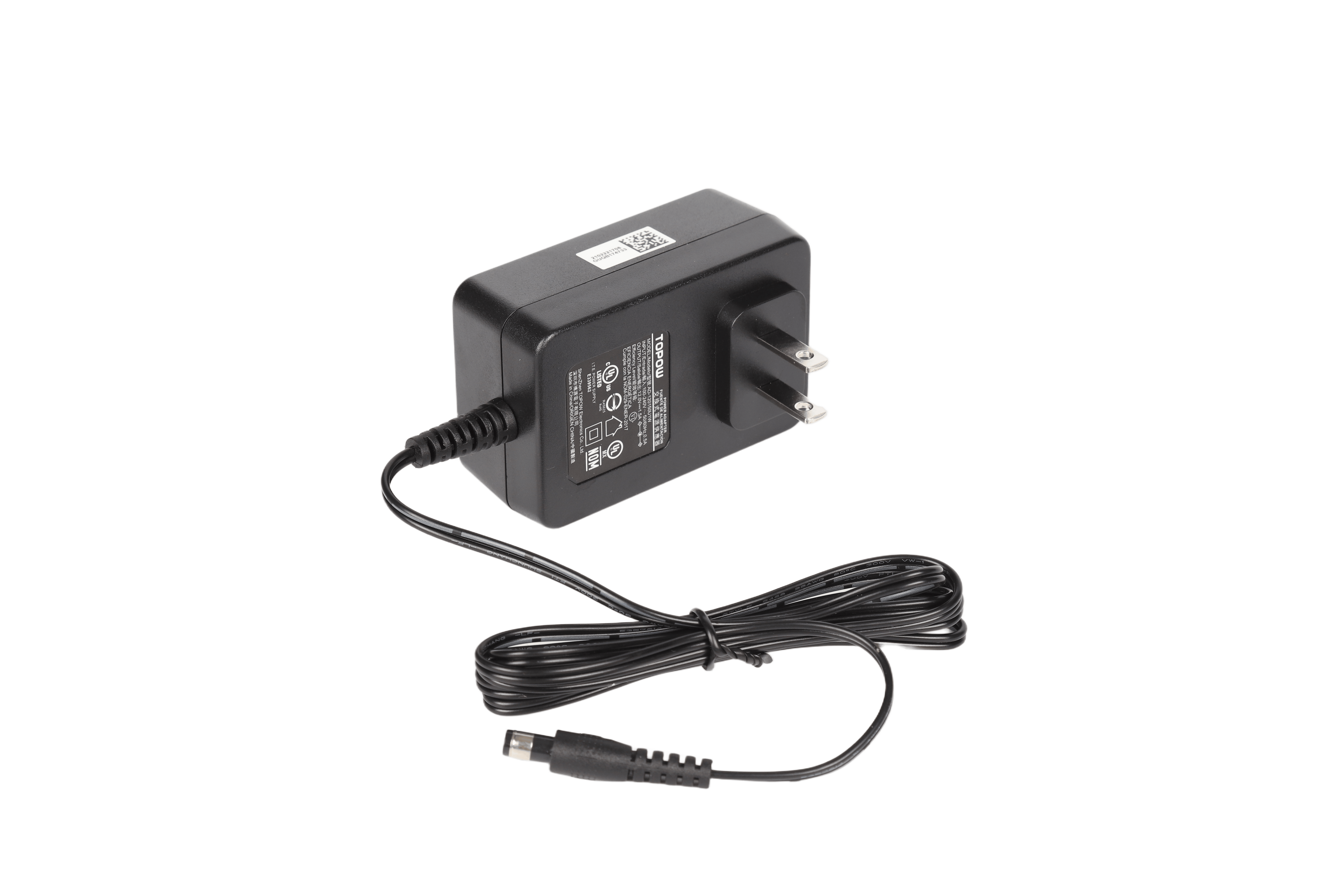
Output Voltage: 12V

Output Voltage Accuracy: 5%

Output Current: 2.5A

MTBF: At least 100,000 hours

Protection: OCP, SCP, OVP

Efficiency: >87.7%

Inrush Current: Cold start 230VAC/60A

Working Temperature: -10~+45°C

Safety Certification: CE ERP

Packing: 0.164kg /80pcs/14kg

Warranty Period: 2 Years


Product Detail

1 Overview

This specification specifies the detailed specifications of the 30W (12V/2.5A) custom power adapter designed and developed by our company.


2 function description

The power adapter can complete the conversion from AC to DC, 90Vac~264Vac input can work normally, rated 12V/2.5A DC output, European plug. The operating temperature is -5 degrees to 45 degrees, with its own shell and natural heat dissipation. The power supply has the functions of input over-current protection, input pressure-sensitive protection, input under-voltage protection, output over-voltage protection, and output over-current protection. The power supply meets the energy efficiency level VI (COC V5 T2).


3 Power supply environmental specifications

Table 1 Environmental Specifications Table


project

unit

Minimum

Typical value

Max

Remarks

Operating temperature

-5

25

45


Storage temperature

-40

25

70


Relative humidity

%

5

/

95

No condensation

Altitude

m

0

/

5000

High temperature derating under 3000~5000m use conditions, 1℃ for every 200m increase

Heat dissipation

/

/

/

/

Natural heat dissipation


4 Electrical characteristics

4.1 Input characteristics

4.1.1 Basic input characteristics

Table 2 Input the basic characteristics table


project

unit

Minimum

Typical value

Max

Remarks

Rated input voltage range

Vac

100

110/220

240


Input voltage range

Vac

90

110/220

264

The long-term input of the highest 318Vac will not be damaged, and it will be accepted according to 4 hours (not working); input undervoltage will not be damaged.

AC input voltage frequency

Hz

47

50/60

63


Input Current

A

/

/

/

Low voltage full load

Input impulse current

A

/

/

60

1. 220Vac input, cold start, meeting standard requirements: ETSI300132-3;

2. Cooperate with 10A, B trip curve MCB, simulate adapter plug-in or power-off and call-on scenarios, the MCB cannot be tripped


No-load power consumption

W

/

/

0.075

Rated input at room temperature

AC input system

/

/

Single phase input

/

Single phase input

30W European standard(图1)
Figure 2 ETSI300132-3 impulse current standard diagram


4.1.2 Input protection features

Table 3 Input protection characteristics


Project

unit

Minimum

Typical value

Max

Remarks

Input undervoltage protection

/

/

/

/

Self-recoverable, long-term input undervoltage is not damaged

Input overcurrent protection

/

/

/

/

1. There is a fuse at the AC input, and the adapter needs to be safely isolated from the grid after an internal short circuit/overload; 2. The selection of overcurrent protection devices must consider that there is no risk of melting the shell under abnormal conditions

Pressure sensitive protection

/

/

/

/

After the pressure-sensitive lightning strike is damaged, it is necessary to ensure that the main circuit of the adapter input is disconnected


4.2 Output characteristics

4.2.1 Basic output characteristics

Table 4 Output basic characteristics table


project

unit

Minimum

Typical value

Max

Remarks

Rated output power

W

/

30

/

90~264Vac full range input

Output voltage range

Vdc

11.4

12

12.6

Full voltage input range, full load output

Output efficiency

%

87.7

/

/

Meet COC V5 T2 energy efficiency requirements, rated input at room temperature, the average efficiency measured at 25%, 50%, 75%, and 100% load is not less than 87.7%; the efficiency measured at 10% load is not less than 77.7 %.

Stabilization accuracy

%

/

/

±5

Full voltage input range, full load output

Source adjustment rate

%

/

/

±2

Rated current output, full voltage range change

Hello Elena

%

/

/

±3

Rated voltage input, full load change

Noise + ripple (peak-to-peak value)

mV

/

/

120

It is carried out within the full input voltage and load range, and a 0.1uF ceramic or gold film capacitor and a 10uF electrolytic capacitor are connected to the output terminal during the test. The bandwidth of the oscilloscope is 20MHz

Dynamic response recovery time

us

/

/

200

25%~50%~25% or 50%~75%~50% load change, current change rate 0.1A/us, cycle 4ms

Dynamic response overshoot

%

/

/

±5

25%~50%~25% or 50%~75%~50% load change, current change rate 0.1A/us, cycle 4ms

Switch overshoot

%

/

/

±5


Output voltage rise time

ms

/

/

200

The output voltage rises from 10% to 90%, rated load

Boot delay time

s

/

/

3


Shutdown hold time

s

/

/

/

no request

Temperature Coefficient

%/

/

/

±0.02

Rated output voltage and output current, full range of operating temperature

Capacitive load

uF

/

/

2000

When the output is connected to a 2000uF capacitor with full load, the output rises monotonically when the output starts


4.2.2 Output protection features

Table 5 Output protection characteristics table


project

unit

Minimum

Typical value

Max

Remarks

Output overvoltage protection point

Vdc

13.5

/

16

Hiccup protection mode, no damage

Output overcurrent protection point

A

3

/

4.5

Hiccup protection mode, long-term over-current and short-circuit without damage

Output short circuit protection

/

/

/

/

Long-term short circuit, hiccup protection mode, self-recovery, no damage


4.3 Other requirements

Table 6 Other requirements table

project

Claim

Remarks

Odor requirements

No peculiar smell and unhealthy smell


Device requirements

Refer to the general specifications of the device.


Failure isolation

The output overvoltage caused by the adapter, the adapter can turn off the output.


Environmental requirements

Meet 2002/95/EC;

No cadmium, hydride and fluoride; polymer substances must be marked; no organic compounds can be emitted; no asbestos; packaging must be recyclable.


Testing requirements

The adapter test needs to follow Huawei's "Outsourced Customized Power Adapter Test Guide V3.0", and deliver the report to Huawei


Process requirements

1. The automation rate of adapters with annual shipments of more than 1000WPCS reaches 95% and above;

2. PCBA is required to be 100% free from cutting feet.

3. Satisfy "Checklist_V2.5, Key Points of Outsourcing Adapter Design"


Automation rate = (SMT device + AI/RI device) number/number of components that can be automated in the industry (except for special-shaped devices);


5 Safety requirements

5.1 Basic requirements

This power supply has obtained safety certification in the form of an independent product, which meets the requirements of its corresponding safety standards, and does not have any impact on the certification of the final product it uses. This product at this stage and in the future meets the requirements of the latest version of the following standards .

5.2 Safety certification requirements

Expected shipping area

AC plug form

AC plug name

Safety certification requirements

Transfer from CB report

Europe

30W European standard(图2) 

European style

CE

can

Meet the standards: meet the requirements of IEC/EN 62368-1, obtain the 62368 standard safety certification CE certificate, and obtain the COC VI t2 energy efficiency certification

5.3 Safety standards

Table 7 List of safety standards


Safety standard

Safety standard content

IEC 60950-1

‘Information technology equipment – Safety. Part 1: General requirements’, plus all existing national and group differences within the IECEE CB Scheme

EN 60950-1

Information technology equipment – Safety. Part 1: General requirements’, plus all existing national and group differences

IEC/EN 62368-1

Audio/Video, Information and Communication Technology Equipment Part 1: Safety requirements


5.4 Key items of safety test

Table 8 Safety test requirements

Test items

Safety requirements

Altitude, insulation and distance

The altitude meets 5000m;

For AC/DC power supply: The power supply meets the requirements of reinforced insulation and distance required by the standards listed in Table 9. This product can meet the requirements and will not affect the international safety certification of the final product.


Secondary circuit

All secondary circuits meet the requirements of the safety special ground voltage circuit (SELV) required by the standards listed in Table 9.

Withstand voltage and ground continuity test

During the production process, the power supply is subjected to 100% withstand voltage test and ground continuity test. The test voltage is in accordance with the requirements of the standards listed in Table 9.

Temperature and humidity test

The temperature and humidity test is a test in the power certification test, and the test is included in the CB report. The test parameters must be determined in accordance with the requirements of the standards listed in Table 9.

In the standard IEC60950, the requirement for temperature and humidity test is 40℃, 120 hours. After the temperature and humidity test, the withstand voltage test is performed immediately. The test results are included in the CB test report.


Insulation resistance test

This test is included in the CB report.

Capacitor discharge test

The capacitor discharge test is a test in the power supply certification test, which is included in the CB report.

Ball pressure test

The ball pressure test is a test in the power certification test, which is included in the CB report. All thermoplastics carrying dangerous voltages (> 42.4 Vpeak or> 60 VDC) are subjected to this test (for example: transformer spools, AC input connectors). The test parameters are required in accordance with the standard IEC60950-1.

Touch current test

The contact current of the power supply complies with the standards listed in Table 9 and the limit requirements of GR-1089-CORE.

Evaluation of components

The key safety parts meet the requirements of the corresponding IEC international standards or the requirements of the standards listed in Table 11.

Primary cable insulation

The color of the insulation layer of the AC input live wire and neutral wire should be brown and blue respectively.

Varistor between input and protective ground

Type A pluggable power supply does not allow a varistor to be connected between the input and the protective ground (Austria, Belgium, Denmark, Finland, Norway, the United Arab Emirates and other countries are not allowed).

LPS requirements

In the positive/abnormal condition of the power supply, the power output meets the requirements of LPS and meets the requirements of UL/IEC/EN60950-1 section 2.5.

5.5 Production line test requirements

100% withstand voltage test of the power supply during the production process

The ground continuity test is performed at the on and off positions of the input switch.

Table 9 Production line test requirements

Test items

Specific requirements

Remarks

Insulation voltage

(1) The primary to secondary should be able to withstand 50Hz, 3000VAC withstand voltage for 1 minute, leakage current ≤ 10mA, no breakdown or arcing;

The equivalent DC voltage can be used for testing.

Insulation resistance

Normal atmospheric pressure, relative humidity <90%, under non-condensing conditions, when the test voltage is 500VDC, the insulation resistance between the primary and the secondary is ≥100MW


Leakage current

<0.25mA (264VAC, 60Hz input)


5.6 Other

Meet the requirements of TT, TN, IT power distribution system, and pass the corresponding certification.

Rated area: When the rated input and output are fully loaded, the room temperature is 25°C, and the housing temperature is required to be less than 75°C.

Zone I: When the rated input and output are at full load, high temperature, the housing temperature is required to be less than 85 degrees,

Under abnormal conditions (overload, short circuit, etc.), the housing temperature is required to be less than 95 degrees (outer surface temperature).

The altitude must meet the 5000m requirement.


6 EMC requirements

Table 10 EMC requirement table


project

Index requirements

standard

Conducted interference

AC port: Class B, the monomer meets a margin of 6dB or more in the R&D stage, and a margin of 4dB or more in the mass production stage

Refer to related standards such as EN55032, grounding/ungrounding meets the requirements, full load range.

Radiation interference

CLASS B, the monomer meets a margin of more than 6dB in the research and development stage, and a margin of more than 4dB in the mass production stage.


SURGE

Differential mode: ±4kV, impedance 2ohm, common mode: ±6kV, impedance 2ohm.

When the structure is not changed, the PCB is compatible with 6KV/6KVsurge.

Waveform 1.2/50us, criterion B;

Remarks:

1. Output no-load/with-load (no-load, half-load, and full-load conditions in the single test test) meet the requirements;

2. Both grounding and ungrounding of the output terminal should be tested;

3. It is necessary to consider the ±10% instrument deviation of different certification agencies.

Criterion B description: During the interference application process of the EUT and after the interference application is completed, the voltage change of the DC output port is within the accuracy range declared in its specification, and the instantaneous change within 1ms is ignored, and it is not allowed to cooperate with the whole machine. A power-down reset of the whole machine occurs.


Reference standard ITU-T K.21

Remarks: 1. The current version shall be accepted according to 4kV/6kV. 2. The current version of PCB has 6kV/6 kVsurge capability.


EFT

AC port:

EFT criterion B

±2kV


IEC61000-4-4


DIP

AC port

1. Drop to 0, duration 10ms, drop at 0°, 45°, 90°, 135°, 180°, 225°, 270°, 315°, and meet criterion B;

2. It drops to 0, lasts 20ms, and all phases meet criterion B at 0°, 45°, 90°, 135°, 180°, 225°, 270°, 315°;

3. Drop to 70% UT, duration 500ms, and all phases at 0°, 45°, 90°, 135°, 180°, 225°, 270°, 315° meet criterion B;

4. Drop to 0%UT, duration 5000ms, all phases at 0°, 45°, 90°, 135°, 180°, 225°, 270°, 315° meet criterion C;

Remarks: only for high voltage input


IEC61000-4-11

ESD

Criterion B

Contact discharge: ±8kV

Air discharge: ±15kV


IEC61000-4-2


CS

AC port CS LEVEL 3; criterion A; 10V

IEC61000-4-6

(You need to use an oscilloscope to monitor the output voltage. There can be glitches, but there can be no instantaneous interruption and long-term interference. The waveform needs to be reflected in the test report)

RS

 Level 3; Criterion A; 10V/m field strength

IEC61000-4-3

(You need to use an oscilloscope to monitor the output voltage. There can be glitches, but there can be no instantaneous interruption and long-term interference. The waveform needs to be reflected in the test report)

Voltage fluctuation and flicker

Voltage fluctuations and flicker limits for class A products

IEC61000-3- 3

Current harmonic emission

Harmonic current limit for class A products

IEC61000-3- 2


Performance criterion:

A: Performance is not allowed to change, or the change is within the range specified in the product specification.

B: During the testing process of the equipment, the performance degradation is allowed within the scope of the product specification. After the interference is eliminated, the equipment can return to normal without resetting and manual intervention in any way.

C: During the test, the equipment allows temporary service interruption, and device damage is not allowed. After the test is completed, the device can recover by itself, or it can be recovered in the background or remote operation (software intervention). No hardware intervention is allowed on the device (such as plugging and unplugging a single board, hardware reset, etc.).

R: During the test, the equipment is allowed to have business interruption, and after the test is completed, it is allowed to recover by itself or manual intervention (including hardware intervention); only the primary protection device is allowed to be damaged during the test, and after the damaged primary protection device is replaced, the equipment can Back to normal.


7 Mechanical structure requirements

7.1 Shape, interface terminal

    See Annex 1, Annex 2

7.2 Labels, nameplates

See Annex 3

7.3 Appearance

See Annex 4


8 Environmental test requirements

8.1 Routine environmental test

Table 11 Routine environmental test requirements table

Serial number

Pilot projects

Reference standards/test parameters

Preliminary stage

Positive stage

Small batch stage

Remarks

1

(Low Temperature Work)

Use environment minimum temperature test

Test duration: 24h


Must do(Increase the test of voltage bias)

2

(High Temperatrue Work)

Use environment maximum temperature test

Test duration: 24h


Must do(Increase the test of voltage bias)

3

(Low Temperature Storage)

-40℃,24h


Must do

4

(High Temperature Storage)

7024h


Must do

5

(Humidity Cross)

indoor:2540℃,95


Must do

6

(Temperatrue Cycling)

indoor:-10℃~45


Must do

7

(Thermal Shock)

-40℃~70


Module must do

Adapter optional


8

(Vibration Test)

5-9Hz, 3.5mm;

9-200Hz:1g; acceleration 10m/s2, 3 axes, 5 sweeps per axis.


Must do

9

(Shock Test)

Acceleration 100m/s2; pulse width 11ms;

3 axes and 6 directions, 3 times in each direction: ±3 times in each axis


Must do

10

 (Drop Test)

Drop to the cement surface, height 1m, 1 corner, 3 edges, 6 sides, each drop once


Must do

11

Temperature derating curve


not involving

12

Output DC plug insertion force test

Test the insertion force with the socket of the whole machine: 30N MAX Pull-out force: 5N~20N; for details, please refer to the following "ONT Power Adapter DC Plug Insertion-Pull Force Test Operation Guide"


Must do

13

Tensile test

5kgf;1min


Must do

14

Bending Test

Angle: ±90°; Frequency: Wire 60 times (single pendulum)/min, DC connector and SR root wire 60 times (back and forth)/min


Must do

15

Cord Pull Test

Lift 5kg, hold for 1min, and test the entire adapter (including plugs of wires and accessories)


Must do

16

Ultrasonic welding strength test

The product is fixed, the ultrasonic welding seam is pulled apart at a speed of 10mm/min, and the pulling force required to pull the upper and lower shells apart is recorded. This force must be greater than 200N


Must do

17

Low temperature bending test of output wire

Immediately after storing for 24 hours at a low temperature of -30 degrees, bend the SR root wire at 90 degrees for 5 times, and the output line and SR cannot be broken


Must do

8.2 Packaging and transportation experiment

Table 12 Test Requirements for Packaging and Transportation

Serial number

Pilot projects

Reference standards/test parameters

Preliminary stage

Positive stage

Small batch stage

Remarks

1

Random vibration

Frequency Acceleration Spectral Density

5Hz: 0.01/Hz;

100Hz: 0.01/Hz;

200Hz: 0.001/Hz;

Total root mean square acceleration: 1.14Grms

Test axis: 3 axis.

Test time: X axis 40min; Y axis 10min, Z axis: 10min


Packages (mandatory for all A-type packages and mandatory for B-type packages less than 100kg)

Test quantity: 3pcs

Subject to shipping packaging


2

Shock

Impact waveform: half sine wave; peak acceleration: 300m/s2; pulse width: 6ms; impact axis: 6 directions; number of impacts: 3 times in each direction


Package

3

collision

Collision waveform: half sine wave; peak acceleration: 180m/s2; pulse width: 6ms; collision direction: 6 directions; collision number: 100 times in each direction.


Package

4

fall

Surface, corner, edge drop:

Weight range Drop height

50~68kg, 46cm

40~50kg, 50cm

30~40kg, 61cm

20~30kg, 80cm

10~20kg, 100cm

≤10kg, 120cm

Drop 4 corners, 3 edges and 6 faces:

4 corners: If one of the bottom corners can be judged to be the weakest, this bottom corner will be used as the falling object; if it cannot be judged, choose the corner 2-3-5. Others are: angle 3-4-5, angle 1-2-5, angle 1-2-6

3 edges: The three edges that intersect at this bottom corner.

6 surfaces: the six outer surfaces of the package;

Number of drops: 2 times for each part


Package

5

Static pressure test

TL = Wt × (S-1) × F ×9.8(N)

Among them: TL: the applied pressure value, the unit is N; Wt: the weight of the package itself, the unit is kg; S: the number of layers allowed to be stacked, select the maximum number of stacked layers; F: the safety factor, usually we choose 5; S=3/hh——The height of the package, in m. The time of applying pressure is maintained for 2h.


Mandatory for paper packaging, optional for wooden packaging

9 Reliability requirements

9.1 MTBF requirements

Table 13 MTBF index table

index

Index requirements

unit

condition

Remarks


MTBF


6


Ten thousand hours

25℃, rated input, rated output load

Reference standard: Telcordia SR332


9.2 Power supply service life requirements

Table 14 Power supply service life

project

Index requirements

Test Conditions

Remarks

Electrolytic capacitor life

3 years

30℃ ambient temperature; rated voltage input (110Vac/220Vac); full load output

1. Life evaluation adopts the measured temperature of electrolytic capacitor;

2. Ambient temperature refers to the working environment temperature of the product.


5 years

30 degree environment, rated voltage input, (110Vac/220Vac) 80% output load

Life evaluation adopts the measured temperature of electrolytic capacitor;


10 packs

See Annex 5


11 Schematic and circuit diagram

See Annex 6


12 Bill of Materials

See Annex 7