Product

>
<

AC DC 12V 1A 12W power adapter desktop certificate CB CE CCC

TPA269-12120-T2

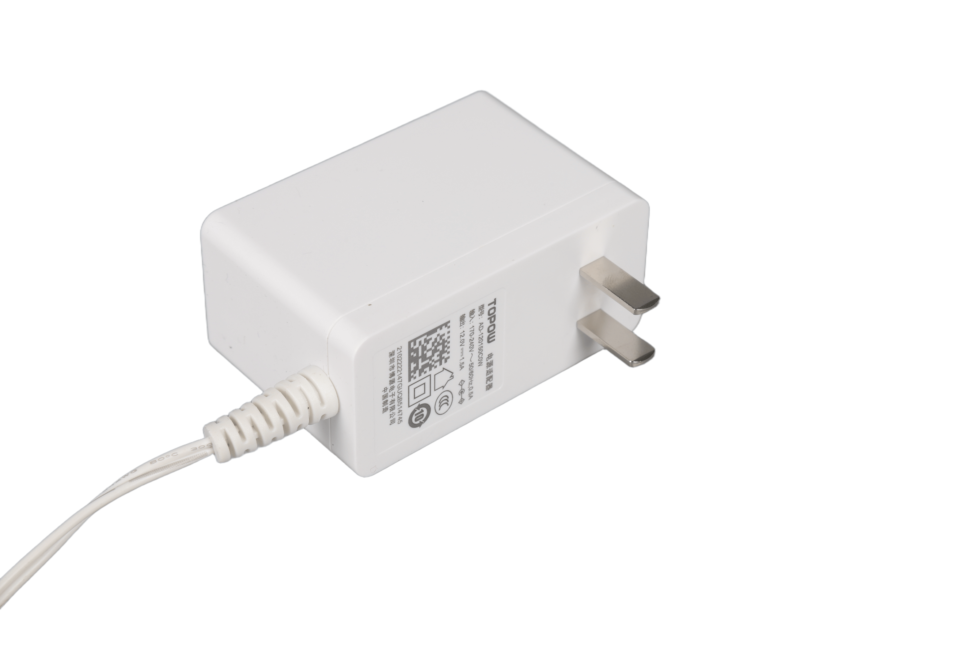
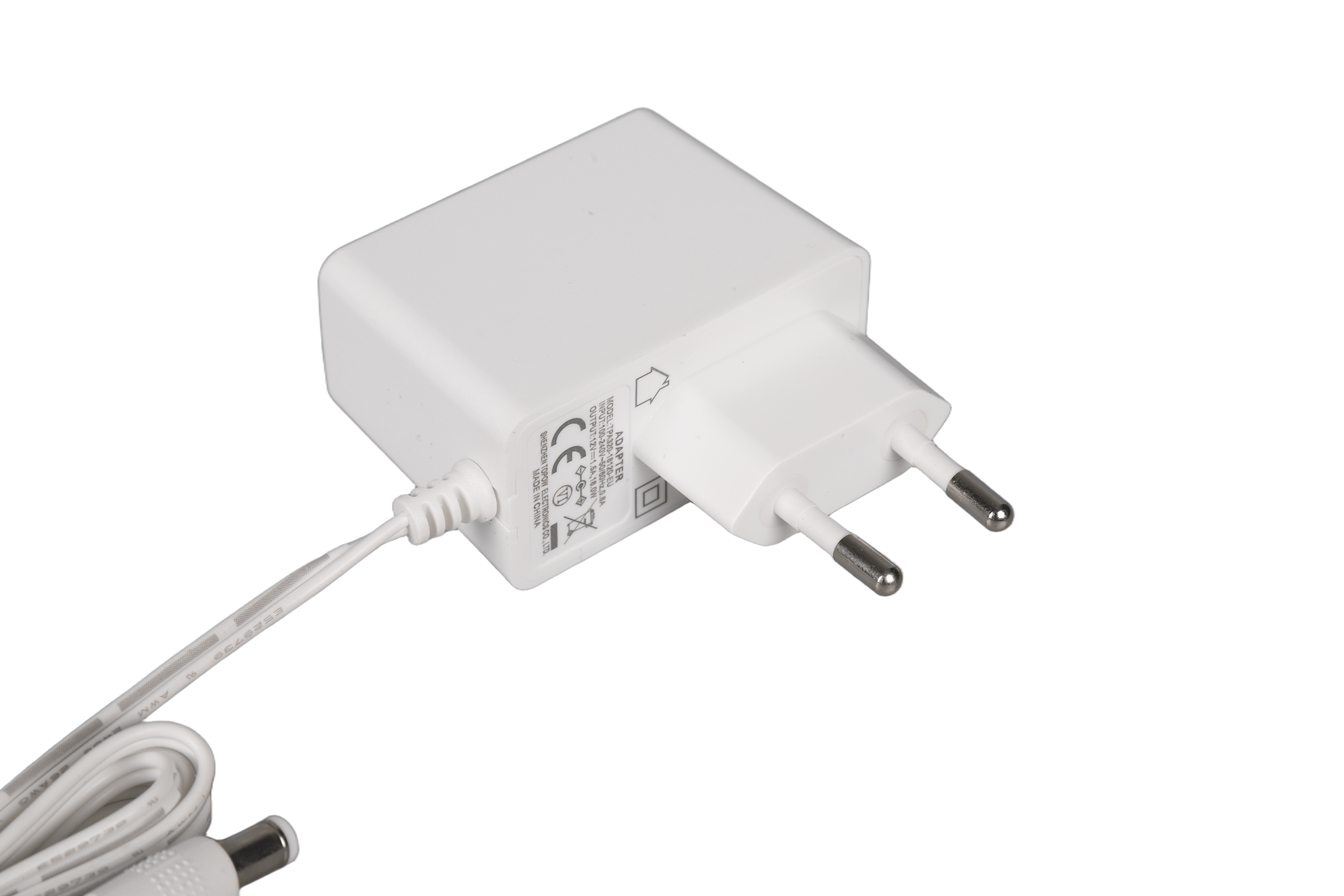
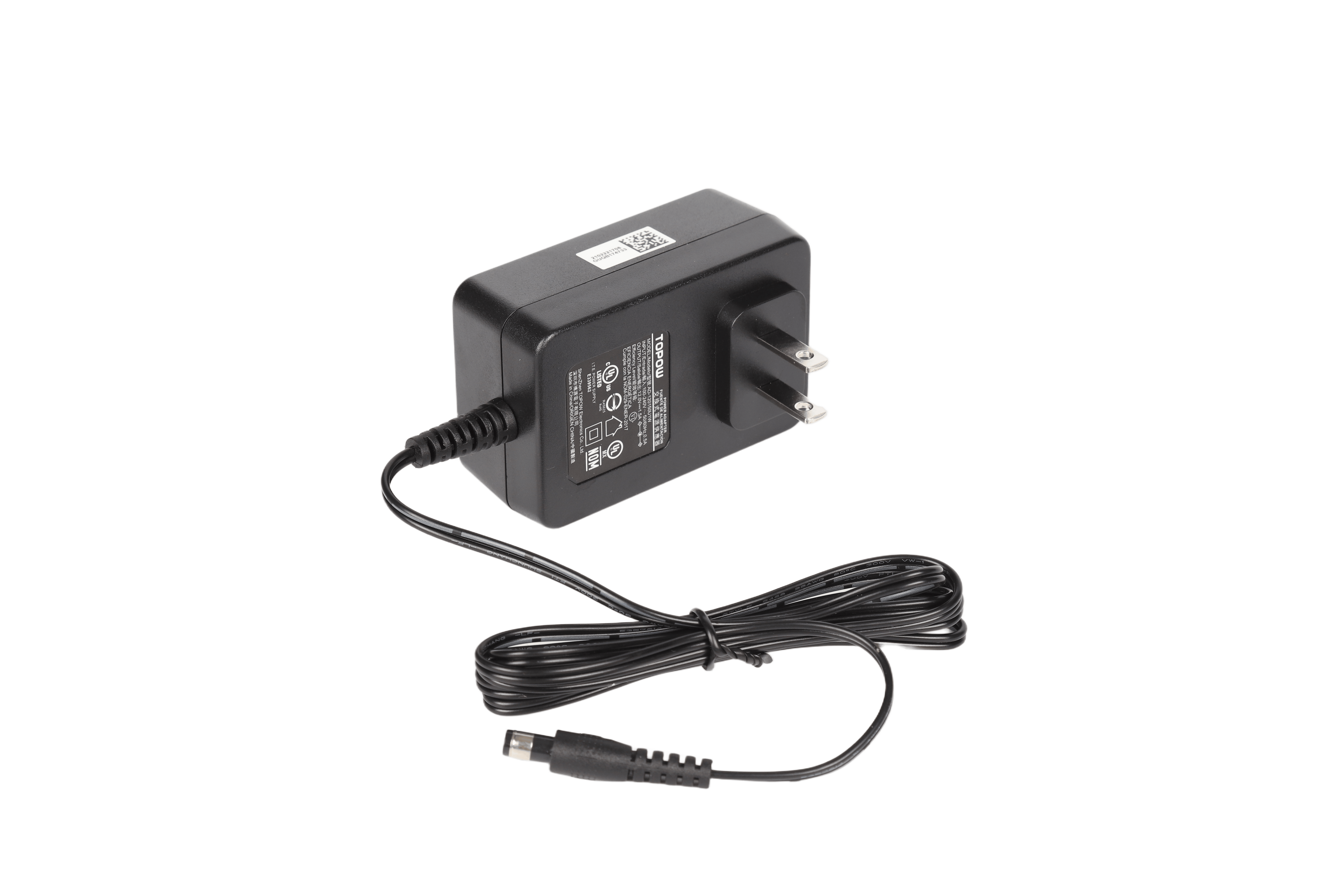
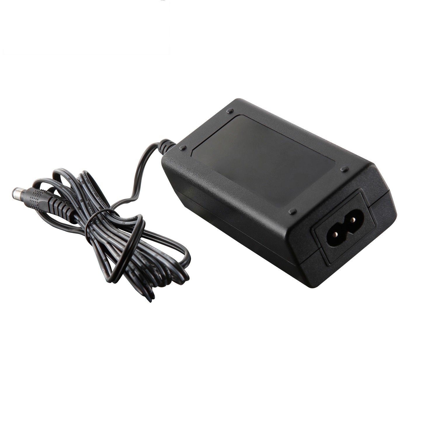
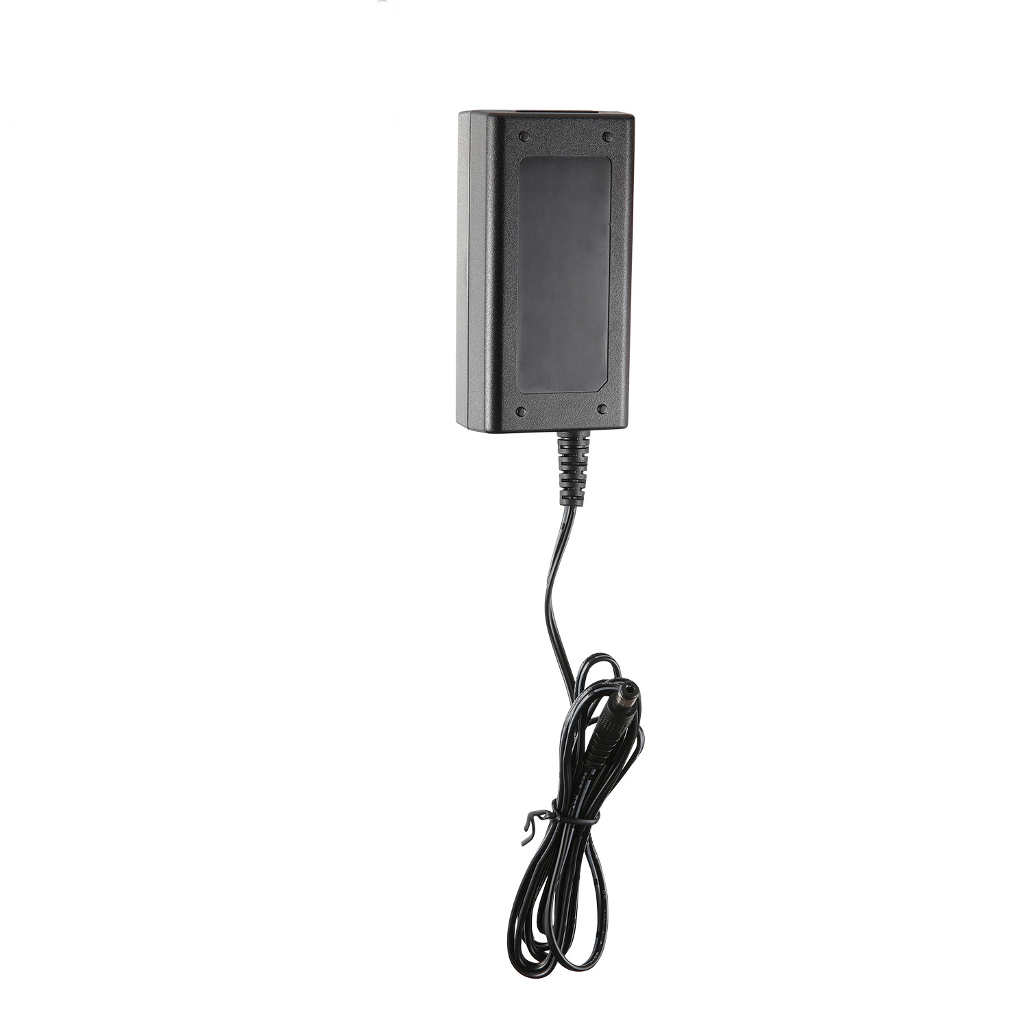
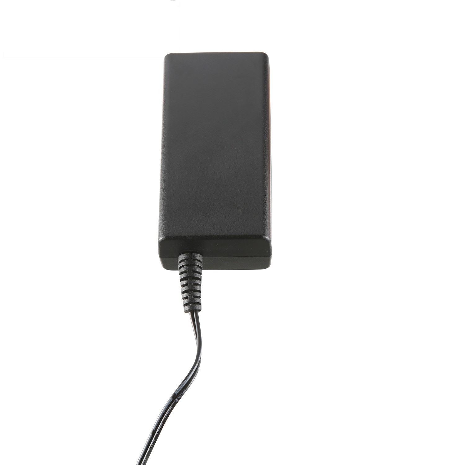
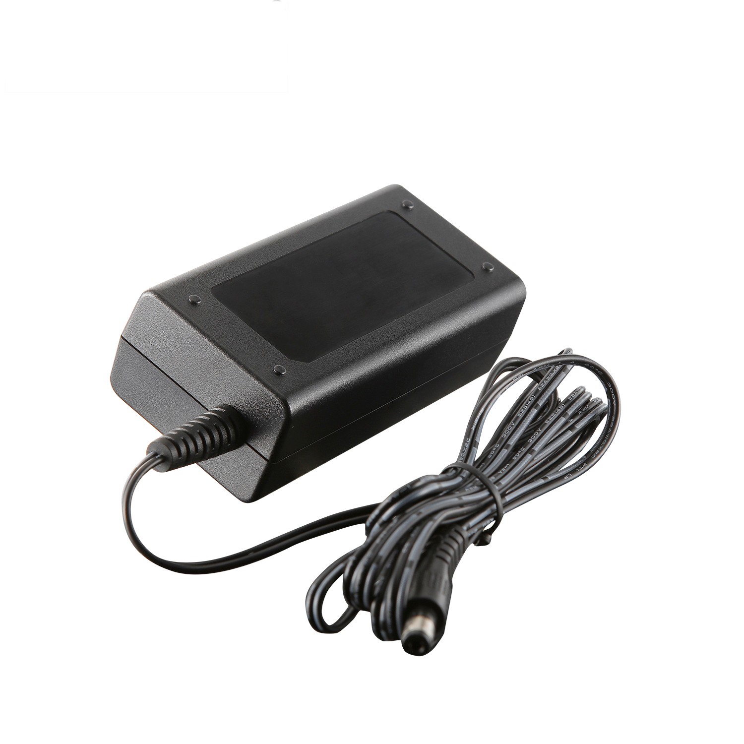
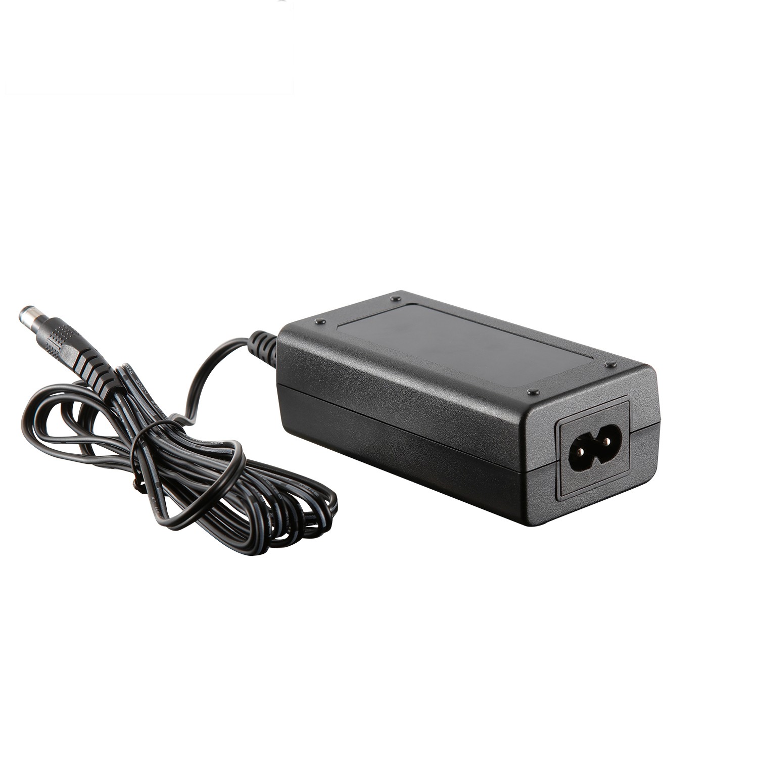
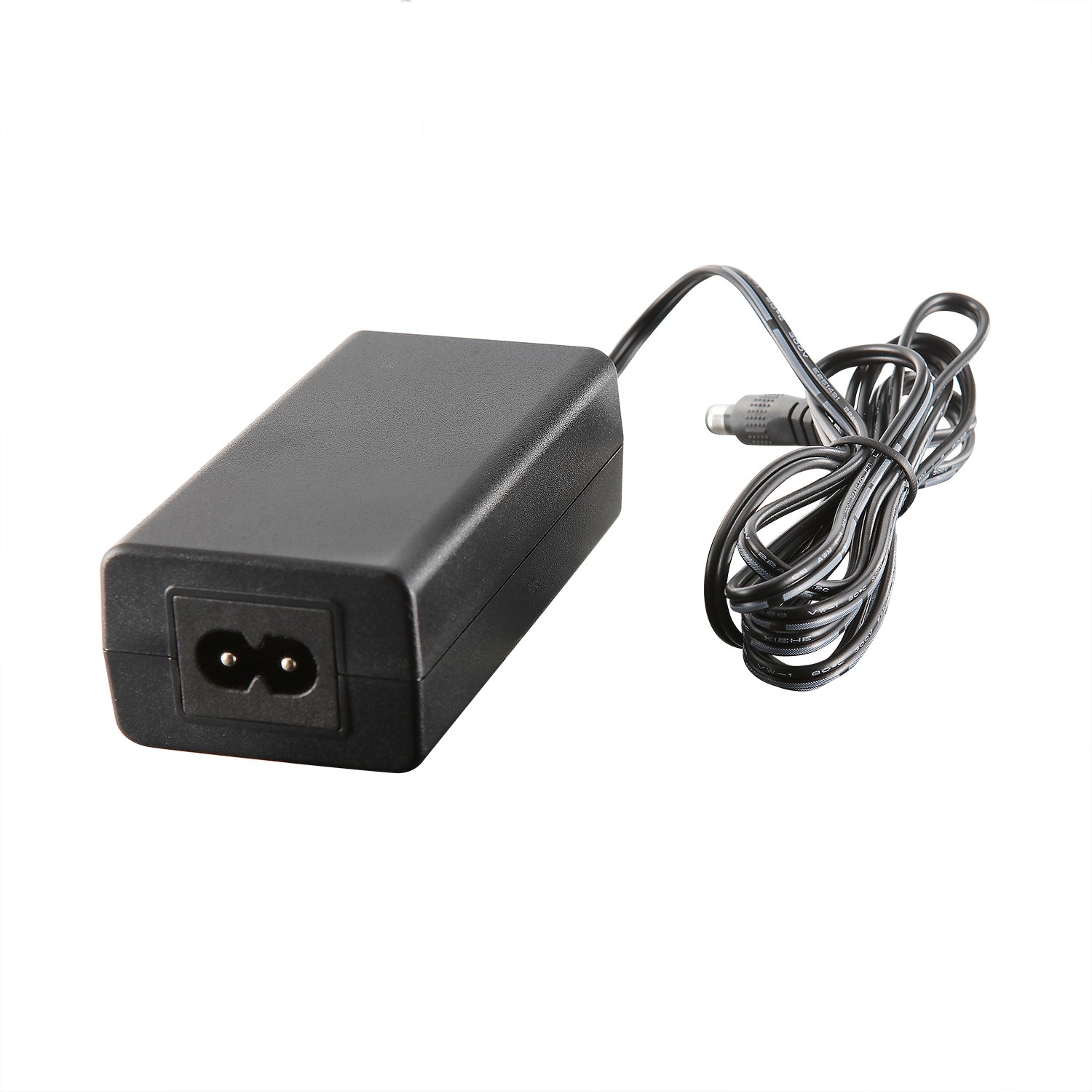
Appearance color: black

Pin type: Desktop type, C8 seat

Output power: 12W

Input voltage: 90~264VAC

Input frequency: 47~63Hz

Output voltage: 12V

Output voltage accuracy: 5%

Output current: 1.0A

Mean time between failures: at least 100,000 hours

Protection: OCP, SCP, OVP

Efficiency: >83%

Inrush current: cold start 230VAC/30A

Working temperature: -10~+45°C

Safety certification: CCC, CB, CE

Packing: 0.11kg/100pcs/11.5kg

Warranty period: 2 years


Product Detail

1 Overview

This specification specifies the detailed specifications of the 12W (12V/1A) custom power adapter designed and developed by our company.


2 function description

The desktop adapter can complete the conversion from AC to DC, 90Vac~300Vac input, rated 12V/1A DC output. The operating temperature range is -40℃ to 55℃, with its own shell, natural heat dissipation, and PCBA design with indicator light. The power supply has functions such as output over-current protection, output over-voltage protection, short-circuit protection, etc., meeting the energy efficiency requirements of ERP6/COC V5 T2.

3Use environment

Table 1 Environmental Specifications Table


Item

Unit

Minimum

Typical value

Maximum

Remarks

Working temperature

-40

25

55

It is required to work normally at low temperature of -40℃, and no need for smoothing of the start-up waveform, and no secondary start-up

Storage temperature

-40

25

70


Relative humidity

%

5

/

95

No condensation

Altitude

m

0

/

5000


Heat dissipation

/

/

/

/

Natural heat dissipation


4 Electrical characteristics

4.1 Input characteristics

4.1.1 Basic input characteristics

Table 2 Input the basic characteristics table

project

unit

Minimum

Typical value

Max

Remarks

Rated input voltage range

Vac

100

110/220

240


Input voltage range

Vac

90

110/220

300

Input 318VAC high voltage is not damaged, 4 hours acceptance

AC input voltage frequency

Hz

47

50/60

63


Input impulse current

A

/

/

60A

Start cold state, input 264VAC; meet the standard requirements: ETSI300132-3

Cooperate with 10A, B trip curve MCB, simulate adapter plug-in or power-off and call-on scenarios, MCB cannot be tripped


No-load power consumption

W

/

/

0.075

Meet the energy efficiency requirements of level VI

Light load and high efficiency

W

/

/

0.25

Input power is less than 0.5W@230VAC

AC input system

/

/

Single phase input

/

Single phase input

AC DC 12V 1A 12W power adapter desktop certificate CB CE CCC(图1)

Figure 2 Standard diagram of impulse current ETSI300132-3

4.1.2 Input protection features

Table 3 Input protection characteristics


project

unit

Minimum

Typical value

Max

Remarks

Input undervoltage protection point

Vac

/

/

/

Self-recoverable, long-term input undervoltage is not damaged

Input undervoltage recovery point

Vac

/

/

/

/

Input overcurrent protection

/

/

/

/

There is a fuse at the AC input, and the main circuit fuse and protective fuse are required to be designed separately.

Insurance placement diagram:


AC DC 12V 1A 12W power adapter desktop certificate CB CE CCC(图2)Remarks: Disable fuse resistance


4.2 Output characteristics

4.2.1 Basic output characteristics

Table 4 Output basic characteristics table


project

unit

Minimum

Typical value

Max

Remarks

Rated output power

W

/

12

/

90~300Vac full range input

Output voltage range

Vdc

11.4

12

12.6

Full voltage input range, full load output

Output efficiency

%

83.26

/

/

Meet ERP6/COC V5 T2 energy efficiency requirements

Stabilization accuracy

%

/

/

±5

Full voltage input range, full load output

Source adjustment rate

%

/

/

±2

Rated current output, full voltage range change

Hello Elena

%

/

/

±3

Rated voltage input, full load change

Noise + ripple (peak-to-peak value)

mV

-10℃~55℃ ambient temperature

It is carried out within the full input voltage and load range, and a 0.1uF ceramic or gold film capacitor and a 10uF electrolytic capacitor are connected to the output terminal during the test. The bandwidth of the oscilloscope is 20MHz


/

/

120


mV

-40℃~-10℃ ambient temperature, test ripple noise after 30 minutes of warming up


/

/

240


Dynamic response recovery time

us

/

/

200

25%~50%~25% or 50%~75%~50% load change, current change rate 0.1A/us, cycle 4ms.

Dynamic response overshoot

%

/

/

±5

25%~50%~25% or 50%~75%~50% load change, current change rate 0.1A/us, cycle 4ms.

Switch overshoot

%

/

/

±3

Full voltage input range, full load output

Output voltage rise time

ms

/

/

200

1. The temperature is -40℃~-25℃, the input voltage is tested from 110Vac, the output voltage rises from 10% to 90%, and the rated load does not require a smooth start.

2. Temperature -25℃~55℃, output voltage rises from 10% to 90%, rated load.


Boot delay time

s

/

/

3s

1. The temperature is -40℃~-25℃, the input voltage is tested from 110Vac, the startup delay time is 3s, and the smooth start-up is not required.

2. The temperature is -25℃~55℃, it requires full input voltage, full load range test, and the startup delay time requires 3s.


Shutdown hold time

s

/

/

/

Meet the DIP requirements in the EMC list

Temperature Coefficient

%/℃

/

/

±0.02

Rated output voltage and output current, full range of operating temperature.

Capacitive load

uF

/

/

2000

1. The temperature is -40℃~-25℃, the input voltage is tested from 110Vac, it is required to start up, and it does not require smooth starting.

2. The temperature is -25℃~55℃, and it requires full input voltage and full load range test. When starting with full load, the output voltage will increase monotonously.


4.2.2 Output protection features

Table 5 Output protection characteristics table


project

unit

Minimum

Typical value

Max

Remarks

Output overvoltage protection point

Vdc

13.5

/

16

Hiccup protection, no damage; SSR scheme sets upper and lower limits;

Output overcurrent protection point

A

1.2

/

2

After the fault is eliminated, it can be restored with full load

Output short circuit protection

/

/

/

/

Long-term short-circuit, self-recovery at full load after the short-circuit fault is eliminated


4.3 Indicator requirements

Table 6 Power adapter indicator requirements


Indicator

colour

Illuminance

normal status

Output overvoltage, overcurrent, short circuit

No output voltage


Output indicator

green

/

bright

Flashing

Extinguish


4.4 Other requirements

Table 7 Other requirements

project

Claim

Remarks

Odor requirements

No peculiar smell or smell harmful to health


Device requirements

Refer to the latest version of "Outsourcing Adapter Development and Design Guide" and "Adapter Device Checklist"


Failure isolation

The output overvoltage caused by the adapter, the adapter can turn off the output


Environmental requirements

Need to meet RoHS 2.0 EU 2015/863, prohibit the use of 4 phthalate substances (DEHP, BBP, DBP, DIBP) (for all electrical and electronic equipment)

Meet RoHS 2.0 EU 2015/863

special requirements

1. No Y capacitor design on the original secondary side

2. If the product involves phone voice, a voice test is required. For test requirements, see the remarks.

3. Add foam to the top of the input high-voltage electrolytic capacitor to absorb electrolyte when abnormal. The temperature of the foam is ≥125 degrees. The fire rating of all materials (including double-sided tape) requires UL94V-0 or equivalent.


Testing requirements

The adapter test needs to be tested in accordance with the latest version of the "Outsourcing Central Office Customized Power Adapter Test Guide"


Process requirements

1. The automation rate reaches 80% 2. PCBA is required to be 100% free of cutting feet

Automation rate = (SMT device + AI device) quantity / quantity of all components

Design requirements

The adapter design needs to be developed and designed in accordance with the latest version of the "Outsourcing Adapter Development and Design Guide"


5 Safety requirements

5.1 Basic requirements

The power supply must obtain safety certification in the form of an independent product and meet the requirements of its corresponding safety standards.

5.2 Safety certification requirements


Expected shipping area

AC socket form

AC outlet name

Transfer from CB

Certification (certification, EMC, energy efficiency)

global

C8

/

Yes

Safety regulations: CCC/CB/CE/

EMC: CE-EMC

Energy efficiency: CoC/ERP


The power supply is required to obtain CCC/CB/CE safety certification. CB and CE require both IEC/EN60950-1 and IEC/EN62368-1 certification standards.

5.3 Safety standards

Table 8 List of safety standards


Safety standard

Safety standard content

GB 4943.1

Safety of Information Technology Equipment (Including Electrical Business Equipment) (standard for China, equivalent to IEC 60950)

IEC 62368-1

Audio/Video, Information and Communication Technology Equipment Part 1: Safety requirements

EN 62368-1

Audio/Video, Information and Communication Technology Equipment Part 1: Safety requirements

IEC 60950-1

‘Information technology equipment – Safety. Part 1: General requirements’, plus all existing national and group differences within the IECEE CB Scheme

EN 60950-1

Information technology equipment – Safety. Part 1: General requirements’, plus all existing national and group differences

PSB

Certification, using IEC 60950 with Singapore National Deviations for external power supply, AC adaptor and trailing brick types only (Singapore). For internal power supplies, CB test report must include 120 Hr. humidity test results.


5.4 Key items of safety test

Table 9 Safety test requirements


Test items

Safety requirements

Altitude, insulation and distance

The altitude is required to meet 5000m;

For AC/DC power supply: The power supply must meet the requirements of reinforced insulation and distance required by the standards listed in Table 10. Suppliers must ensure that their products meet this requirement so as not to affect the international safety certification of the final product.


Secondary circuit

All secondary circuits must meet the requirements of the safety special ground voltage circuit (SELV) required by the standards listed in Table 10.

Withstand voltage and ground continuity test

The manufacturer shall perform 100% withstand voltage test and ground continuity test on the power supply during the production process. The test voltage is in accordance with the requirements of the standards listed in Table 10.

Temperature and humidity test

The temperature and humidity test must be a test in the power certification test, and the test must be included in the CB report. The test parameters must be determined in accordance with the requirements of the standards listed in Table 10.

In the standard IEC60950, the requirement for temperature and humidity test is 40℃, 120 hours. The withstand voltage test must be performed immediately after the temperature and humidity test. The test result must be included in the CB test report.


Insulation resistance test

Japan no longer requires insulation resistance testing.

Although the insulation resistance test is not required in Singapore's national differences, the test result is still required when the final product enters Singapore for evaluation. Therefore, the power supplier must conduct this test and include it in the CB report.


Capacitor discharge test

The capacitor discharge test must be a test in the power certification test, and the test must be included in the CB report.

Ball pressure test

The ball pressure test must be a test in the power certification test, and the test must be included in the CB report. All thermoplastics that carry dangerous voltages (> 42.4 Vpeak or> 60 VDC) must be tested (for example: transformer spools, AC input connectors). The test parameters are required in accordance with the standard IEC60950-1.

Touch current test

The contact current of the power supply must meet the standards listed in Table 10 and the limit requirements of GR-1089-CORE.

Evaluation of components

Suppliers need to provide customers with device samples necessary for evaluation and international certification.

The key safety parts must meet the requirements of the corresponding IEC international standards or the requirements of the standards listed in Table 11.


Primary cable insulation

The color of the insulation layer of the AC input live wire and neutral wire should be brown and blue respectively.

Varistor between input and protective ground

Type A pluggable power supply does not allow a varistor to be connected between the input and the protective ground (Austria, Belgium, Denmark, Finland, Norway, the United Arab Emirates and other countries are not allowed).

LPS requirements

In the positive/abnormal condition of the power supply, the power output meets the LPS requirements and must meet the requirements of UL/IEC/EN60950-1 section 2.5.


5.5 Production line test requirements

100% withstand voltage test of the power supply during the production process

The ground continuity test is performed at the on and off positions of the input switch.

Table 10 Production line test requirements


Test items

Specific requirements

Remarks

Insulation voltage

Primary to secondary should be able to withstand 50Hz, 3000VAC withstand voltage for 1 minute, leakage current ≤10mA, no breakdown or arcing phenomenon;

The equivalent DC voltage can be used for testing.

Insulation resistance

Normal atmospheric pressure, relative humidity <90%, under non-condensing conditions, when the test voltage is 500VDC, the insulation resistance between the primary and the secondary is ≥100MW


Leakage current

<0.25mA (300VAC, 60Hz input)


5.6 Other requirements

Meet the requirements of TT, TN, IT power distribution system, and pass the corresponding certification.

Under normal temperature 25℃, rated input and output full load, the case temperature should be less than 75℃; under 45℃ ambient temperature, under abnormal conditions (overload, short circuit, etc.), the case temperature should be less than 95℃.


6EMC requirements

6.1 EMC certification requirements

Requires power supply to meet CE certification

6.2 EMC requirement table

Table 11 EMC requirements table


project

Index requirements

standard

Conducted interference 

AC port: Class B, single unit:

6dB margin at the R&D stage; 4dB margin at the mass production stage


Reference standard EN55032; full load, grounded and ungrounded tests must be met。

Radiation interference

CLASS B monomer:

6dB margin at the R&D stage; 4dB margin at the mass production stage


SURGE

AC port:

Differential mode: ±6kV impedance 2ohm Common mode: ±6kV, impedance 2ohm

Waveform 1.2/50us, criterion B;

Remarks

1. The output no-load/with-load (no-load, half-load, and full-load conditions in the single test test) must meet the requirements;

2. Both grounding and ungrounding of the output terminal should be tested;

3. It is necessary to consider the ±10% instrument deviation of different certification agencies.

Criterion B description: During the interference application process and after the interference application is completed, the voltage change of the DC output port of the EUT is within the accuracy range declared in its specification. The instantaneous change within 1ms is ignored, and it is not allowed to cooperate with the whole machine. A power-down reset of the whole machine occurs. After the 6KV test fails, no shell burst can occur.


IEC61000-4-5

ITU-T K.21 2008


EFT

AC port: EFT criterion B; ±2KV

You need to use an oscilloscope to monitor the output voltage. There can be glitches, but there can be no instantaneous interruption and long-term interference. The waveform needs to be reflected in the test report.


IEC61000-4-4


DIP

Drop to 0, duration 10ms, drop at each phase of 0°, 45°, 90°, 135°, 180°, 225°, 270°, 315°, meeting criterion B;

When it drops to 0, the duration is 20ms, and all phases of 0°, 45°, 90°, 135°, 180°, 225°, 270°, 315° meet criterion B;

Drop to 70% UT, duration 500ms, and all phases at 0°, 45°, 90°, 135°, 180°, 225°, 270°, 315° meet criterion B;

Drop to 0%UT, duration 5000ms, all phases of 0°, 45°, 90°, 135°, 180°, 225°, 270°, 315° meet criterion C;

Remarks: only for high voltage input (230Vac)


EN 61000-4-11


ESD

Criterion B

Contact discharge: ±8kV

Air discharge: ±15kV


IEC61000-4-2


CS

AC port CS LEVEL 3; criterion A; 10V, 30% deviation of the equipment should be considered.

Need to use an oscilloscope to monitor the output voltage, there can be glitches, but there should be no instantaneous interruption and long-term interference. The waveform needs to be reflected in the test report


IEC61000-4-6

RS

Level 3; Criterion A; 10V/m field strength, 30% deviation of the equipment should be considered.

Need to use an oscilloscope to monitor the output voltage, there can be glitches, but there should be no instantaneous interruption and long-term interference. The waveform needs to be reflected in the test report


IEC61000-4-3

Voltage fluctuation and flicker

Voltage fluctuations and flicker limits for class A products

IEC61000-3- 3

Current harmonics

Harmonic current limit for class A

IEC61000-3- 2


Performance criterion:

Criterion A-Normal performance within the scope of technical requirements;

Criterion B-Some functions can be temporarily deteriorated or lost, and can be self-recovered, but the output voltage must be kept within the normal range during the test;

Criterion C: Automatic reset with short-term functional interruption is allowed, and long-term functional interruption or manual reset is not allowed;

Criterion R: No damage to any device other than the protection device is allowed, and the test piece can recover its performance after replacing the damaged protection device.


7 Mechanical structure requirements

7.1 Shape, interface terminal

See attachment 1

7.2 Nameplate, barcode

See attachment 2


8 Environmental test requirements

8.1 Routine environmental test

Table 12 Routine environmental test requirements table


Serial number

Pilot projects

Reference standards/test parameters

Initial sample

Right kind

Small batch

Remarks

1

(Low Temperature Storage)

-40℃, 24H; after the test, the material is not deformed, and the power supply should not be damaged or performance abnormal (only check the default output voltage, voltage regulation accuracy, output ripple, dynamic response)


Must do

2

Low temperature limit

Do it in a thermostat, the low temperature limit is -40℃. 2 hours. The power supply works normally, and there is no abnormality such as damage.


Must do, can be combined with low temperature storage

3

(High Temperature Storage)

70°C, 24H; after the test, the material is not deformed, and the power supply should not be damaged or abnormal in performance (you can only check the default output voltage, voltage stabilization accuracy, output ripple, and dynamic response).


Must do

4

High temperature limit

Do it in a thermostat, the high temperature limit is 55℃, if over temperature protection, record the temperature before over temperature protection. 2 hours. The power supply works normally, and there is no abnormality such as damage.


Must do, can be combined with high temperature storage

5

High and low temperature impact (working)

-40℃~70℃; no cracking in power supply solder joints and PCB; no falling off of all devices in the power supply; no cracking in the package and body of all devices; no shrinkage of the plastic shell of all devices; basic functions of the power supply must be performed after the test Completely normal


Choose to do

Reference IPC9592


6

High and low temperature impact (storage)

1. Put the unpackaged and non-powered power supply sample into the environmental temperature box, and the temperature will rise from 23°C to 70°C (humidity is arbitrary), and the rate of change is 30°C/h;

2. Stay at 70°C for 72h (humidity is arbitrary);

3. The temperature drops from 70°C to 23°C (humidity is arbitrary), and from 70°C to 23°C within 5 minutes.


Choose to do

Reference IPC9592


7

(Low Temperature Work)

Minimum temperature in specification

Under the rated load condition and the minimum load condition, run for 16 hours each at the rated input voltage, and then the input voltage is the maximum and minimum respectively for 4 hours test. During the experiment, the machine is turned on and off repeatedly, and the power supply should start normally.


Must do

8

(High Temperatrue Work)

Maximum temperature of specification

Under the rated load condition and the minimum load condition, run for 16 hours each at the rated input voltage, and then the input voltage is the maximum and minimum respectively for 4 hours test. During the experiment, the machine is turned on and off repeatedly, and the power supply should start normally.


Must do

9

(Humidity Cross)

indoor:25~40℃,95%

outdoor:25~55/65℃,95%


Must do

10

Temperature derating curve


Choose to do


11

Salt spray test

After the salt spray test, the exposed metal and electroplated parts have no corrosion or rust after the salt spray test. See "Test Guide for Outsourcing Custom Power Adapter"


Metal AC PIN needs to be done

12

HALT test

Low temperature step:

Test stop conditions: indoor power supply -40℃, outdoor power supply -60℃.

Eligibility criteria: The root cause must be analyzed for the failure of the indoor power supply within -40℃~-50℃; the root cause must be analyzed for the failure within -55℃~-60℃. Decisions are needed to make specific changes


Choose to do


High temperature step:

Test stop condition: indoor power supply 100℃. ; Outdoor power supply 110℃.

Eligibility criteria: The root cause must be analyzed for the failure of the indoor power supply within 90℃~100℃; the root cause must be analyzed for the failure of the outdoor power supply within 100℃~110℃. Whether to change the details requires a decision.


Choose to do


Vibration step:

Stop condition: If the vibration stress reaches 40Grms and the operating limit is not found, stop this test item and consider the operating limit to be 40Grms.

Eligibility criteria: failures within 35G of vibration must be modified, and failures within 35-40Grms must be analyzed for the root cause.


Choose to do


Comprehensive stress: no failure


Choose to do


8.2 Packaging and transportation experiment

Table 13 Test Requirements for Packaging and Transportation

Serial number

Pilot projects

Reference standards/test parameters

Initial sample

Right kind

Small batch

Remarks

1

Random vibration

Frequency Acceleration Spectral Density

5~20Hz: 1.0m2/s3;

20~200Hz: -3dB;

Total root mean square acceleration: 0.781Grms

Test axis: 3 axis;

Test time: 30min for each axis.


Package

Mandatory for all A-type packages, and mandatory for B-type packages less than 100kg


2

Shock

Impact waveform: half sine wave; peak acceleration: 300m/s2; pulse width: 6ms; impact axis: 6 directions; number of impacts: 3 times in each direction.


Package

3

collision

Collision waveform: half sine wave; peak acceleration: 180m/s2; pulse width: 6ms; collision direction: 6 directions; collision number: 100 times in each direction.


Package

4

fall

Surface, corner, edge drop:

Weight range Drop height

50~100kg, 30cm

40~50kg, 40cm

30~40kg, 50cm

20~30kg, 60cm

15~20kg, 80cm

≤15kg, 100cm

Drop 1 corner, 3 edges and 6 faces:

1 corner: If one of the bottom corners can be judged to be the weakest, this bottom corner will be used as the falling object; if it cannot be judged, choose the corner 2-3-5.

3 edges: the three edges that intersect at this bottom corner.

6 surfaces: the six outer 5 surfaces of the package;

Number of drops: 1 time on each side


Package

5

Static pressure test

TL = Wt × (S-1) × F ×9.8(N)

Among them: TL: the applied pressure value, the unit is N; Wt: the weight of the package itself, the unit is kg; S: the number of layers allowed to be stacked, select the maximum number of stacked layers; F: the safety factor, usually we choose 5; S=3/hh——The height of the package, in m. The time of applying pressure is maintained for 2h.


Mandatory for paper packaging, optional for wooden packaging

9 Mechanical test requirements

9.1 General mechanical test requirements

Table 14 Conventional mechanical test requirements table

Serial number

Pilot projects

Reference standards/test parameters

Initial sample

Right kind

Small batch

Remarks

1

(Vibration Test)

5-9Hz, 3.5mm; 9-200Hz: 1g; 3 axes, 5 sweeps per axis.


Must do

2

(Shock Test)

Half-sine shock spectrum, 11ms/5g (equipment greater than 100kg) 6 directions, 3 shocks in each direction


Must do

3

Load

1. Initial inspection before the test to ensure that the mechanical and electrical performance of the adapter is normal before the test.

2. Fix the adapter, apply 700N to the shell, and keep it for 2s after the force is reached.

3. It is necessary to check the mechanical and electrical functions of the sample after each side test.

After the test is completed, the mechanical and electrical functions of the product are normal. Allow manual and recoverable mechanical failures to occur.


Must do

4

(Drop Test)

Drop to the cement surface, height 1m, 1 corner, 3 edges, 6 sides, each drop once


Must do

5

Ultrasonic welding strength test

The product is fixed, the ultrasonic welding seam is pulled apart at a speed of 10mm/min, and the pulling force required to pull the upper and lower shells apart is recorded. This force must be greater than 500N.


Must do

6

Shell squeeze test

1. Initial inspection before testing to ensure normal mechanical and electrical performance of the adapter;

2. Fix the adapter, apply 200N squeezing force to the corner or edge of the shell (the weakest position), and the test speed is 10mm/min;

3. Increase the squeezing force and record the maximum breaking force.

The shell must withstand a squeezing force of at least 200N, and the shell cannot open under the squeezing force of 200N, and the AC PIN pin cannot be broken.


Must do

7

(Bending Test)

Angle: ±90°; Frequency: wire 60 times (single pendulum)/min, DC connector and SR root wire 60 times (back and forth)/min, load 200g.


Must do

8

Output wire tension test

Lift a weight of 5kg, hold for 1min, and test the entire adapter (including plugs of wires and accessories).

After the test is completed, the mechanical and electrical functions of the adapter are normal (the shell has no deformation or cracks, the rated input voltage, and the output voltage meets the specifications when working at full load)


Must do

9

Output DC head plug force and plug durability test

1. Test the insertion force with the socket of the whole machine: 30N MAX pull-out force: 5N~20N;

5N≤before test≤20N

3N≤after test≤20N

2. Plug and unplug durability test: 20~30 times/min,

1000 times.

The accessory plug is not damaged, the size of the accessory plug is within the specification, and the contact is good. When the accessory plug is shaken, there is no noise and the function is normal. Before the test, the plugging force after the test should meet the requirements, the mechanical and electrical functions of the plug are normal, and the surface coating of the IO interface is allowed to wear, but no physical damage is allowed.


Must do


10

Low temperature bending test of output wire

Immediately after storing at a low temperature of -30°C for 24 hours, the SR root wire was bent back and forth 5 times at 90 degrees. When bending for the 5th time, the output cable and SR cannot be broken.


Must do

10 Reliability requirements

10.1 MTBF requirements

Table 15 MTBF index table

index

Index requirements

unit

condition

Remarks

MTBF

10

Ten thousand hours

25℃, rated input, rated output load; reference standard: Telcordia SR332

Provide reliability prediction report, which must meet the index requirements

10.2 Power supply service life requirements

Table 16 Requirements for the service life of the power supply

evaluation items

Index requirements

Evaluation conditions

Remarks

Electrolytic capacitor life

5 years

40℃ ambient temperature; rated voltage input (110Vac/220Vac); full load output

1. Life evaluation adopts the measured temperature of electrolytic capacitor

2. A photo showing the test point of the capacitor temperature should be attached to the report


11 packaging

See Annex 4


12 Schematic and circuit diagram

See Annex 5


13 Bill of Materials

See Annex 6