Product

>
<

Factory direct moving constant current black 54V 7.2A 12V/5A dual power supply

TPT450D5412A


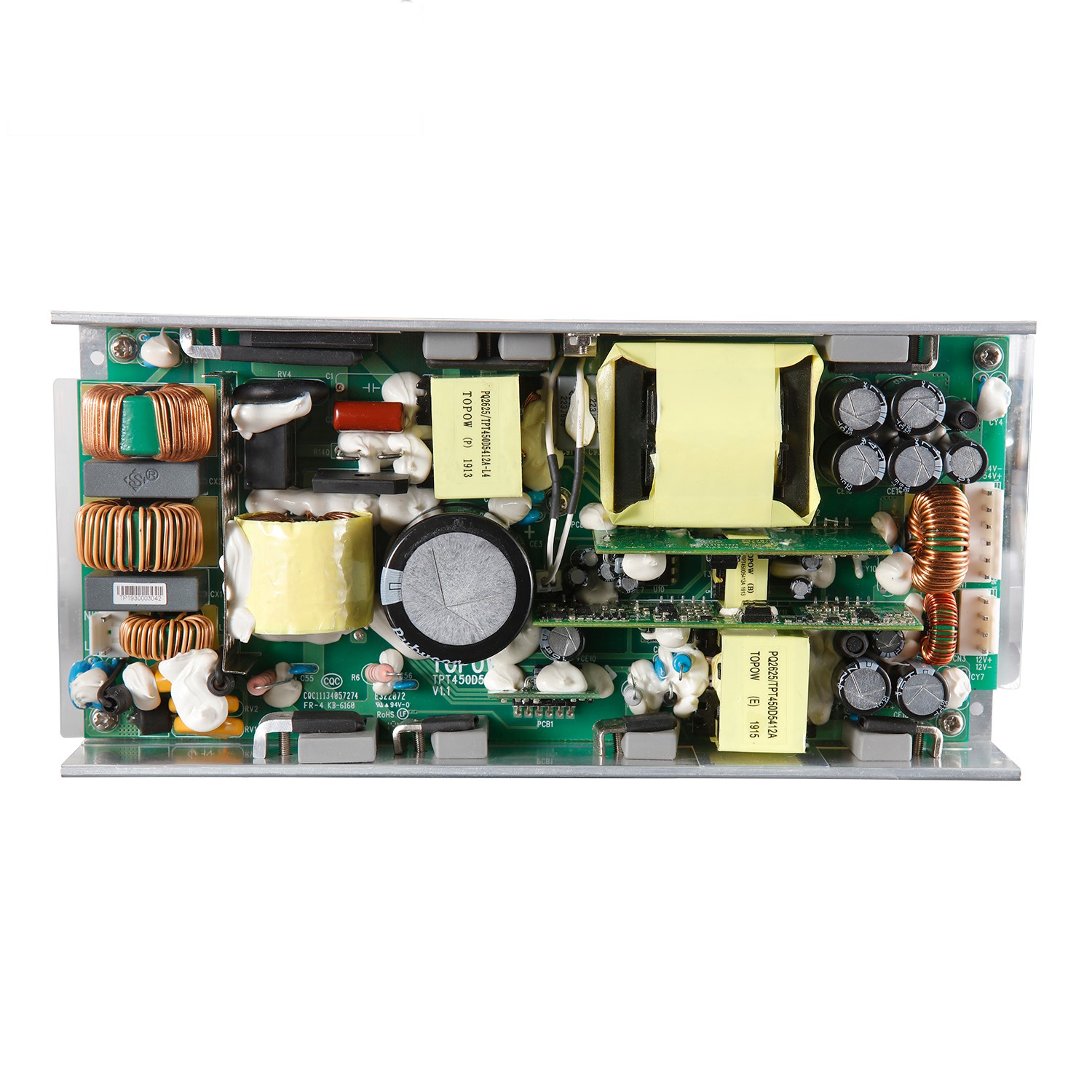
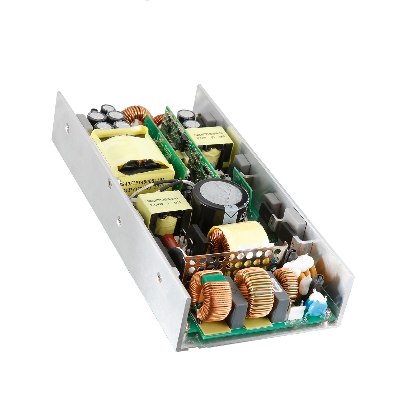
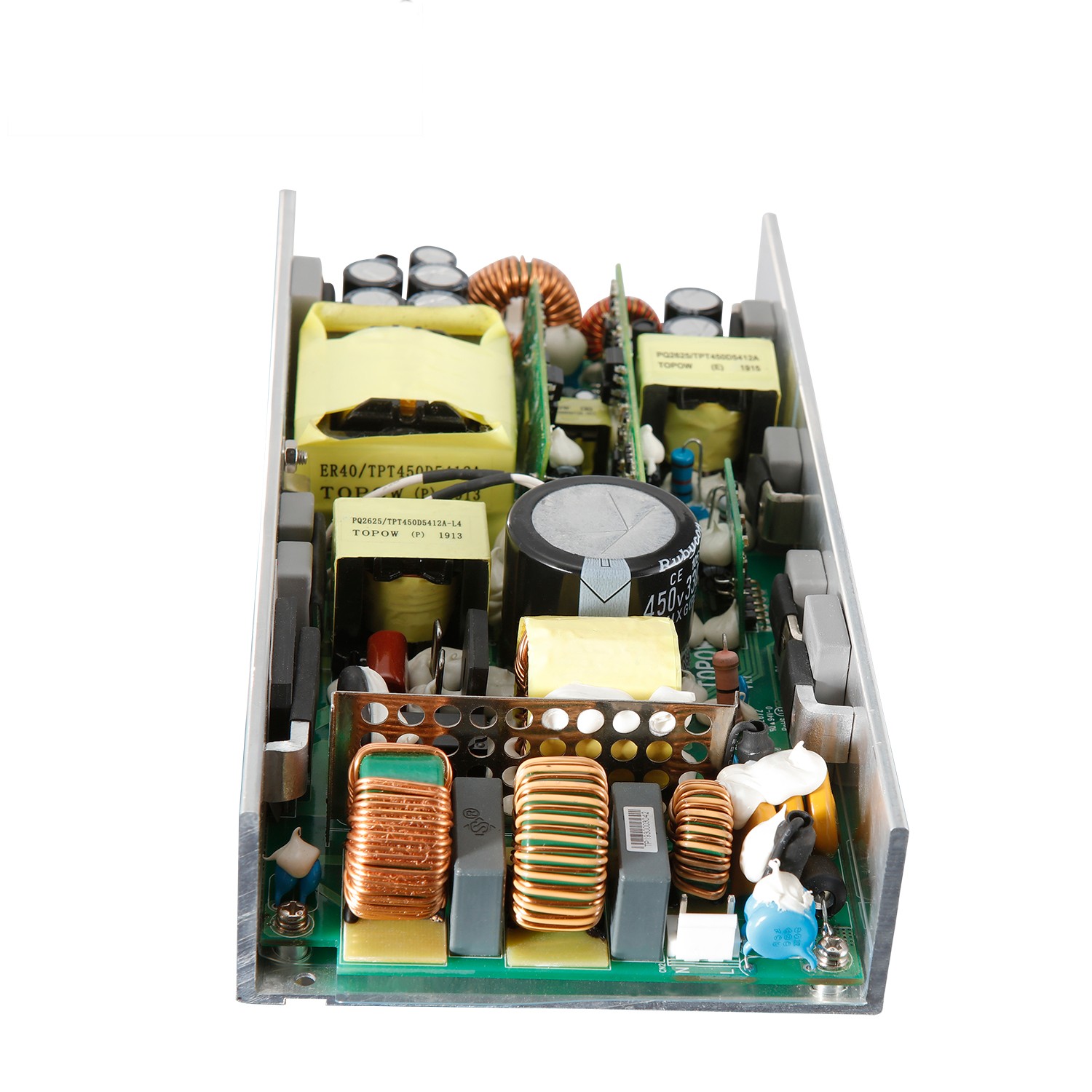
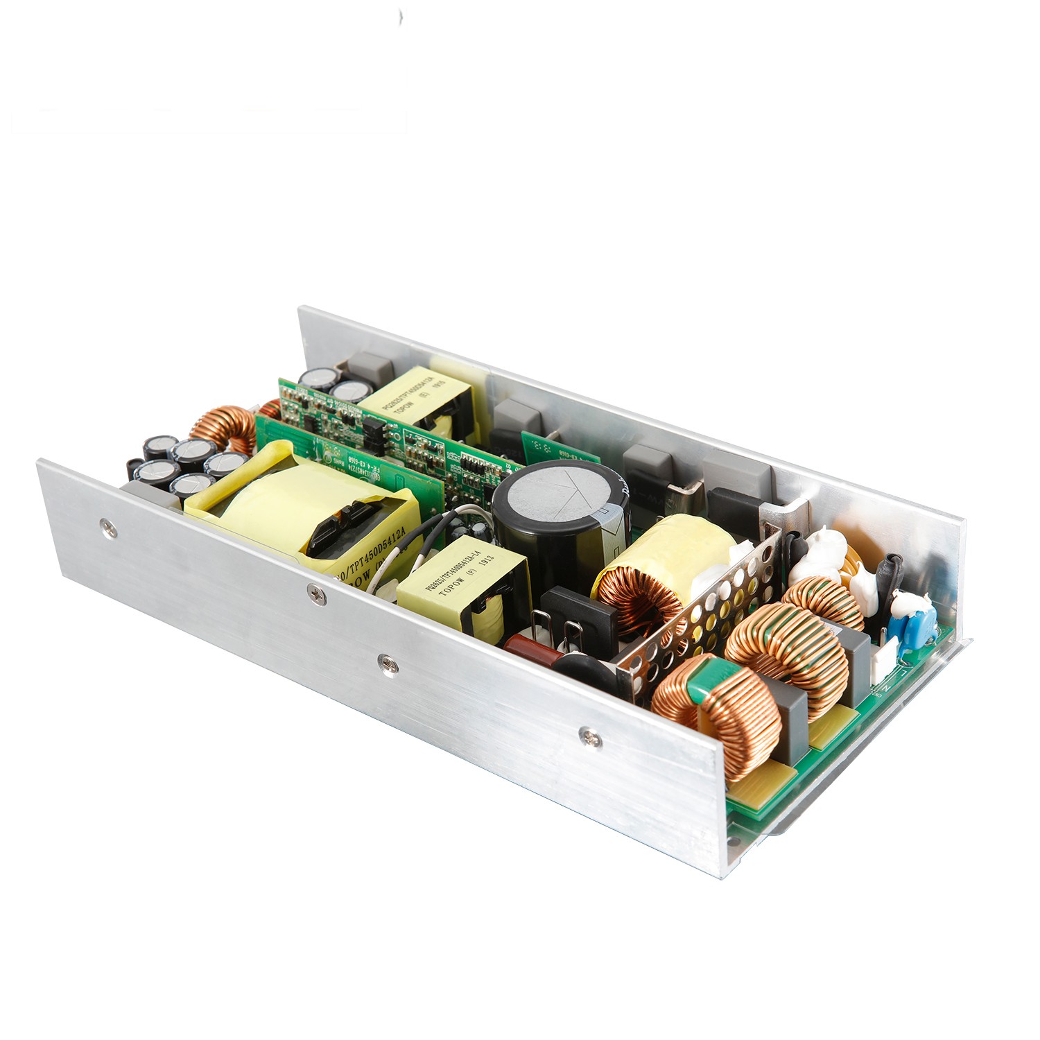
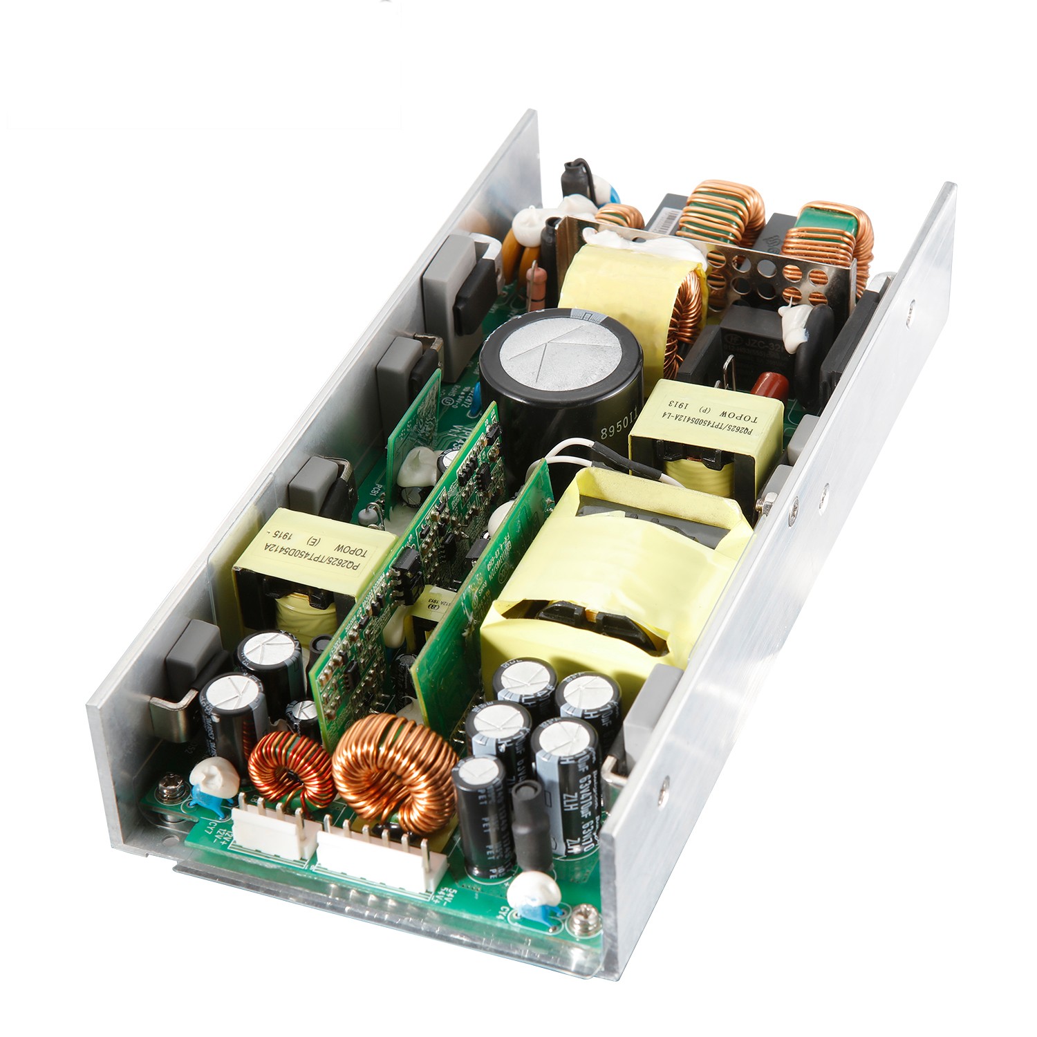
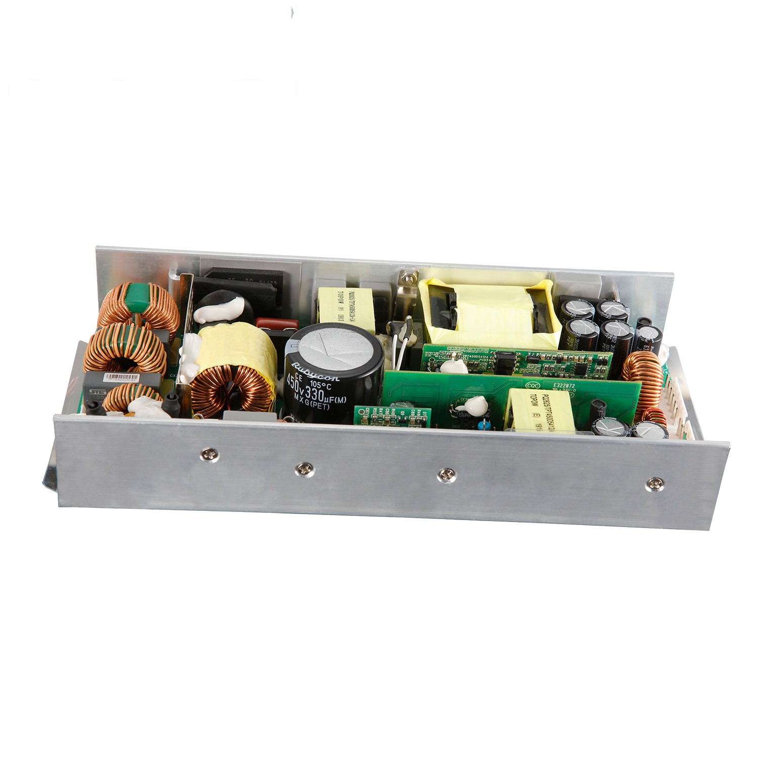
Power supply type: bare board

Output power: 450W

Output type (single or multiple groups?): Double groups

Input voltage: 90~264VAC

Input frequency: 47~63Hz

Output voltage/current: 54V/7.2A 12V/5

Output voltage accuracy: 5%

Mean time between failures: at least 100,000 hours

Protection: overcurrent and overvoltage

Efficiency: more than 88%

Inrush current: 80A/220VAC

Working temperature: -10~+50°C

Warranty period: 2 years


Product Detail

1. POWER SUPPLY OVERVIEW:

1.1 INPUT ELECTRICAL CHARACTERISTICS OVERVIEW

1.1.1 Input voltage range: 90Vac to 264Vac

1.1.2 Nominal input Normal voltage range: 100Vac to 240Vac

1.1.3 Standby power Loss: measured at 100Vac No load

1.1.4 Power Factor PF>0.95 (100-240Vac Input ,Full load)

1.1.5 Max input ac current:5.5Amax at full load condition @90Vac~264Vac INPUT

1.1.6 Inrush current: MAX80A (Cold start), 230Vac input

1.1.7 Input Power (W):550W (max)@Full Load

1.1.8 Efficiency Efficiency: 92%(min) at 240VAC, full load condition;

1.1.9 Leakage Current: Less Than 3.5mA(max),230Vac input

1.1.10 Input Fuse: T15A/250Vac, T10A/250Vac

1.1.11 Operating frequency: variable frequency (measured frequency at 0%, 25%, 50%, 100% load)

1.2 OUTPUT ELECTRICAL CHARACTERISTICS OVERVIEW

1.2.1 OUTPUT VOLTAGE RANGE

Output Voltage

Min value

Normal value

Max value

Requirements

Vout1

51.3V

54V

56.7V

Vin=100Vac240Vac

      Io=7.4A

Maximum Output Capacitance 1000uF

Vout2

11.4V

12V

12.6V

Vin=100Vac240Vac

Io=5A

Maximum Output     Capacitance 470uF

1.2.2 OUTPUT CURRENT RANGE

Output Current

Min value

Normal value

Max value

Requirements

Iout1

0A

7.4A

7.4A

Vin=100Vac240Vac

Iout2

0A

5A

5A

Vin=100Vac240Vac

Note: Iout =0A, Criterion: No damage, hazardous, and resonance

1.2.3 LINE REGULATION

Line Regulation

Min value

Normal value

Max value

Requirements

Vout1: 54V

/

±1%

/

Vin=100Vac240Vac

Io=7.4A

Vout2: 12V


±1%


Vin=100Vac240Vac

Io=5A

1.2.4 LOAD REGULATION

Load Regulation

Min value

Normal value

Max value

Requirements

Vout1: 54V

/

±2%

/

Vin=100Vac240Vac

 Io=7.4A

Vout2: 12V


±2%


Vin=100Vac240Vac

 Io=5A

1.2.5 OUTPUT VOLTAGE TOLERANCE

Output voltage tolerance

Min value

Normal value

Max value

Requirements

Vout1: 54V

/

/

   ±5%

Vin=100Vac240Vac Io=7.4A

Vout2: 12V


   ±5%

Vin=100Vac240Vac Io=5A

1.2.6 OUTPUT RIPPLE & NOISE

Output Voltage

Ripple & Noise (Max.)

Vout: 54V

300mVp-p@25

Vout: 12V

120mVp-p@25

Note: 1) Measurements shall be made with an oscilloscope with 20MHz bandwidth.

2) Outputs shall be bypassed at the connector with a 0.1Uf ceramic capacitor and a 10Uf electrolytic capacitor to simulate system loading.

1.2.7 OUTPUT TRANSIENT RESPONSE

Voltage regulation

Slew Rate

Test Condition: Load Changing Scope

54V ±5%;

0.2A/us

25% to 50% load and 50% to 75% load


12V ±5%;

0.2A/us

25% to 50% load and 50% to 75% load


1.2.8 OUTPUT OVERSHOOT / UNDERSHOOT

Output

Overshoot / Undershoot

Min value

Normal value

Max value

Requirements

Vout1: 12V

/

/

±5%

Iout=0A-7.4A

Vout1: 54V


±5%

Iout=0A-5A

1.2.9 TURN ON TIME


Turn on time

Min value

Normal value

Max value

Requirements

Vout1: 54V

/

5S

/

Vin=230Vac

Io=7.4A

Vout2: 12V


5S


Vin=230Vac

Io=5A

1.2.10 OUTPUT HOLD TIME


Output Hold Time

Min value

Normal value

Max value

Requirements

Vout1: 54V

/

5mSMeasured

/

Vin=230Vac

Io=7.4A

Vout2: 12V


5mSMeasured


Vin=230Vac

Io=5A

1.2.11 OUTPUT RISE TIME

output Rise time

Min value

Normal value

Max value

Requirements

Vout1: 54V

/

50ms

/

Vo=10%-90% Io=7.4A

Vout2: 54V


30ms


Vo=10%-90% Io=5A

1.3 Protection function:

1.3.1 OUTPUT OVER CURRENT PROTECTION

Output over current Protection

Min value

Normal value

Max value

Requirements

Vout1: 54V

9A

/

12A

Hiccup  Auto-recovery mode

Vout1: 12V

6A


8A

Hiccup  Auto-recovery mode

1.3.2 OUTPUT SHORT CIRCUIT PROTECTION.


Output Short Circuit Protection 

Comments


Hiccup  Auto-recovery mode

1.3.3 OUTPUT OVER VOLTAGE PROTECTION


over voltage Protection

Min value

Normal value

Max value

Requirements


Vout1: 54V


56V


/


60V


Hiccup  Auto-recovery mode


Vout: 12V


14


18

Hiccup  Auto-recovery mode

1.3.4 INPUT UNDER VOLTAGE PROTECTION


Input under voltage Protection


1. Turn-On Voltage Threshold (70~90VAC)

2. Turn-Off Voltage Threshold (75~89VAC)

3. Lockout Hysteresis Voltage

(1~5VAC)


Locked, can be restored after the fault is removed and restartedLatch


Input over-voltage protection


1. Turn-On Voltage Threshold (285~320VAC)

2. Turn-Off Voltage Threshold (286~319VAC)

3. Lockout Hysteresis Voltage

(1~5VAC)


Locked, can be restored after the fault is removed and restartedLatch

2. Insulation performance

2.1 ISOLATION RESISTANCE

Requirements

Parameter value

Note

500VDC/25/70%RH

50MΩ

I/P-O/P,I/P-FG,O/P-FG

2.2 ISOLATION WITHSTANDING VOLTAGE

Parameter name

Parameter value

Note

Input To Output

3000Vac/10mA/1min 

No breakdown or flashover phenomenon

Input To PG

1500Vac/10mA/1min

No breakdown or flashover phenomenon

Output To PG

1500Vac/10mA/1min

No breakdown or flashover phenomenon

3. Safety requirements SAFETY:

The design meets the requirements of UL60950 and EN60950 standards.

Design in accordance with UL60950 and EN60950 the requirements of the standard.

4. Electromagnetic compatibility EMC:

4.1 Electromagnetic Interference EMI

The power supply shall comply with the following Criterion:

1) Conduction Emission: EN55022, CLASS B

2) Radiated Emission: EN55022, CLASS B

3) Harmonics: *GB17625.1/ IEC/EN61000-3-2

4) Voltage flicker Flicker & Fluctuation: *GB17625.2/ IEC/EN 61000-3-3

4.2 Electromagnetic immunity EMS

The power supply shall comply with the following Criterion:

1) Electrostatic immunity ESD: *GB17626.2-1998/IEC61000-4-2/ EN 61000-4-2

2) Burst anti-interference EFT: *GB17626.4-1998/IEC61000-4-4 3KV /EN 61000-4-4,

3) Lightning surge Surge: *GB17626.5-1998/IEC61000-4-5 /EN 61000-4-5 Differential mode: 1KV Common mode: 2KV.

4) Voltage Dips: *EN 61000-4-11, IEC 1000-4-11:2001.

5) Radiation immunity RS: *GB17626.3-1998/IEC61000-4-3/ EN 61000-4-3

6) Conducted immunity CS: *GB17626.6-1998/IEC61000-4-6 /EN61000-4-6

7) Power frequency magnetic field immunity PMS: *GB17626.8-1998/IEC61000-4-8 /EN61000-4-8

5. Working environment ENVIRONMENTAL REQUIREMENT

5.1 Products (E-CAP) life calculation MTBF

Lx=Lo*2^((To-Tx)/10) @ 50℃ 5 Year (Over 44000 hours)

5.2 Ambient temperature

5.2.1 Operating temperature: -10℃ to +50℃.

5.2.2 Storage temperature: -20℃ to +70℃.

5.3 Ambient humidity

5.3.1 Operating: From 10%to90% relative humidity (non-condensing).

5.3.2 Store: From 5 to 95% relative humidity (non-condensing).

5.4 Altitude

5.4.1 Operating: to10,000 ft.

5.4.2 Store: to 20,000ft.

5.5 Cooling method: air cooling.

5.6 Vibration Testing

10-55Hz, 49.0m/s²(5G), 3minutes period, 60minutes each along X, Y and Z axis.

5.7 Impact Testing

196.1m/s²(20G),11ms, once each X, Y and Z axis.

5.8 The derating curve is as follows:

Factory direct moving constant current black 54V 7.2A 12V/5A dual power supply(图1)

6. Connector pin definition

7.1.Pin-CON1 DC Connection And Function TYPE: vertical 3.96.0MM*5PIN

NO

Pin Connection

Function

1

L

L-INPUT

2

NG

NG

3

N

N-INPUT

4

NG

NG

5

PE

PE-

7.2.Pin-CON2 Connection And Function TYPE: 3.96MM*4PIN

NO

Pin Connection

Function

1

54V

RETURN

2

54V

RETURN

3

GND

RETURN

4

GND

RETURN

7.3.Pin-CON3 Connection And Function TYPE: 3.96MM*4PIN

NO

Pin Connection

Function

1

12V

RETURN

2

12V

RETURN

3

GND

RETURN

4

GND

RETURN

8. Chart(Unit: mm)
Factory direct moving constant current black 54V 7.2A 12V/5A dual power supply(图2)