Product

>
<

Bare panel low power 12v 3a variable adjustable switching power supply

TPT36S12A

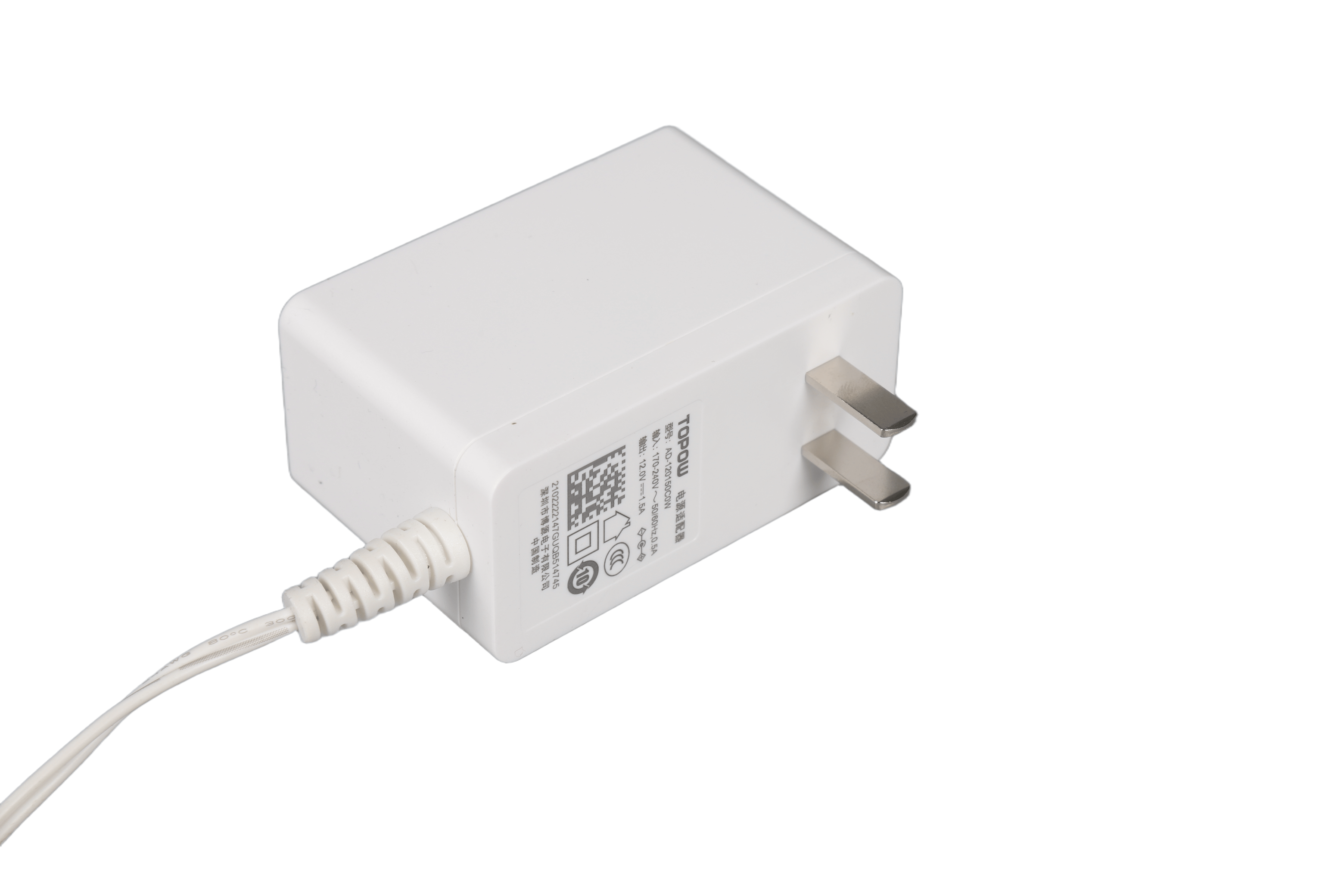
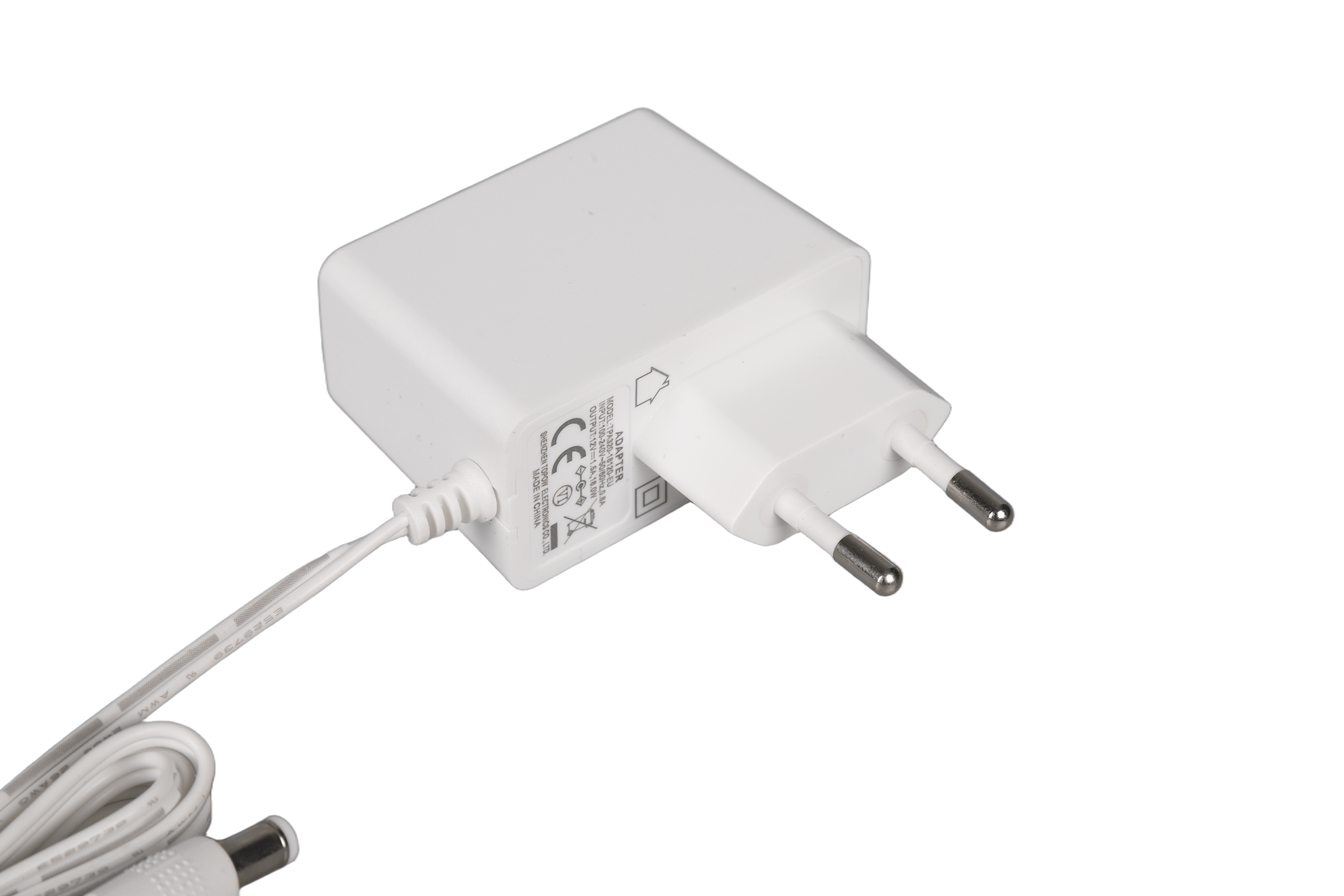
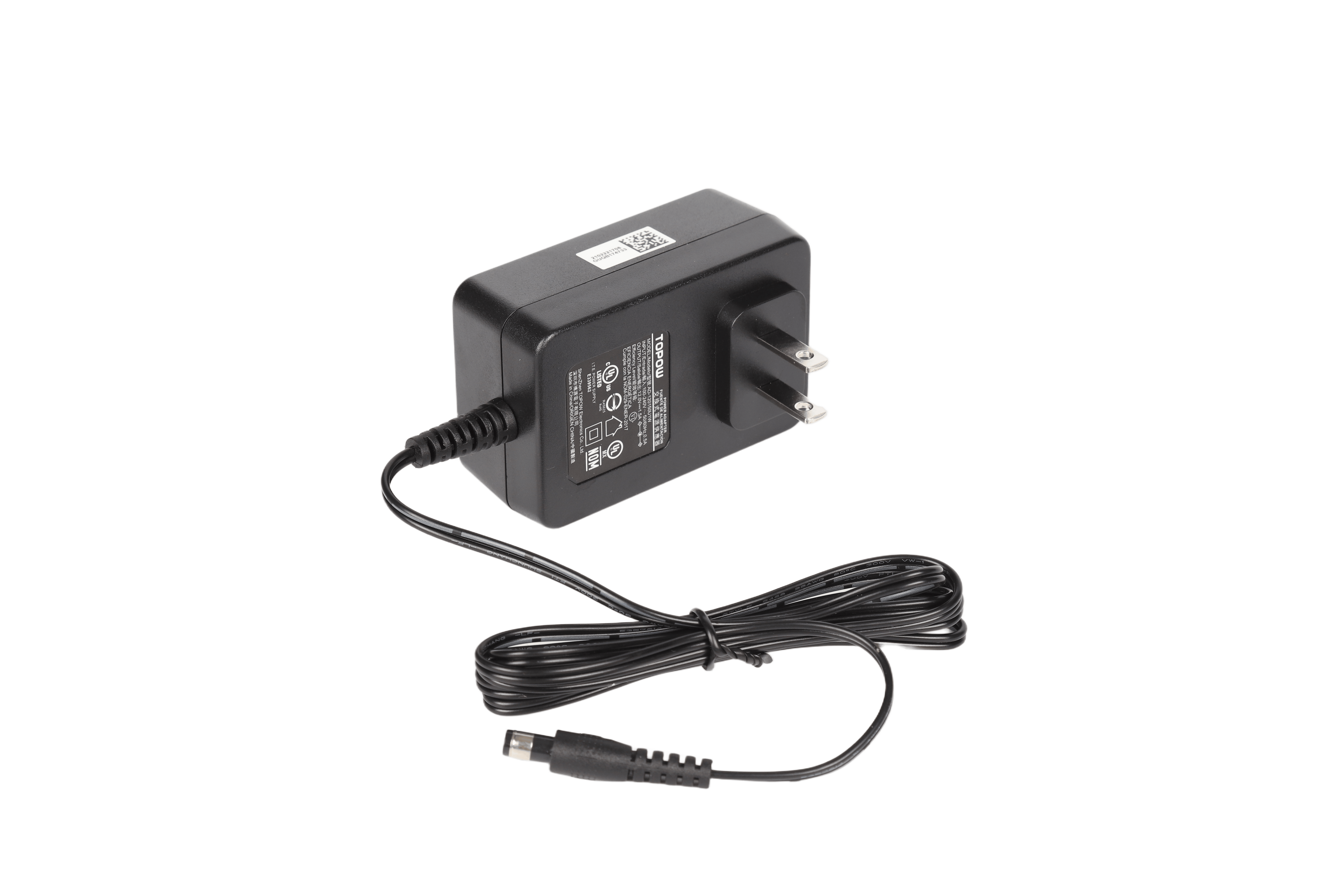
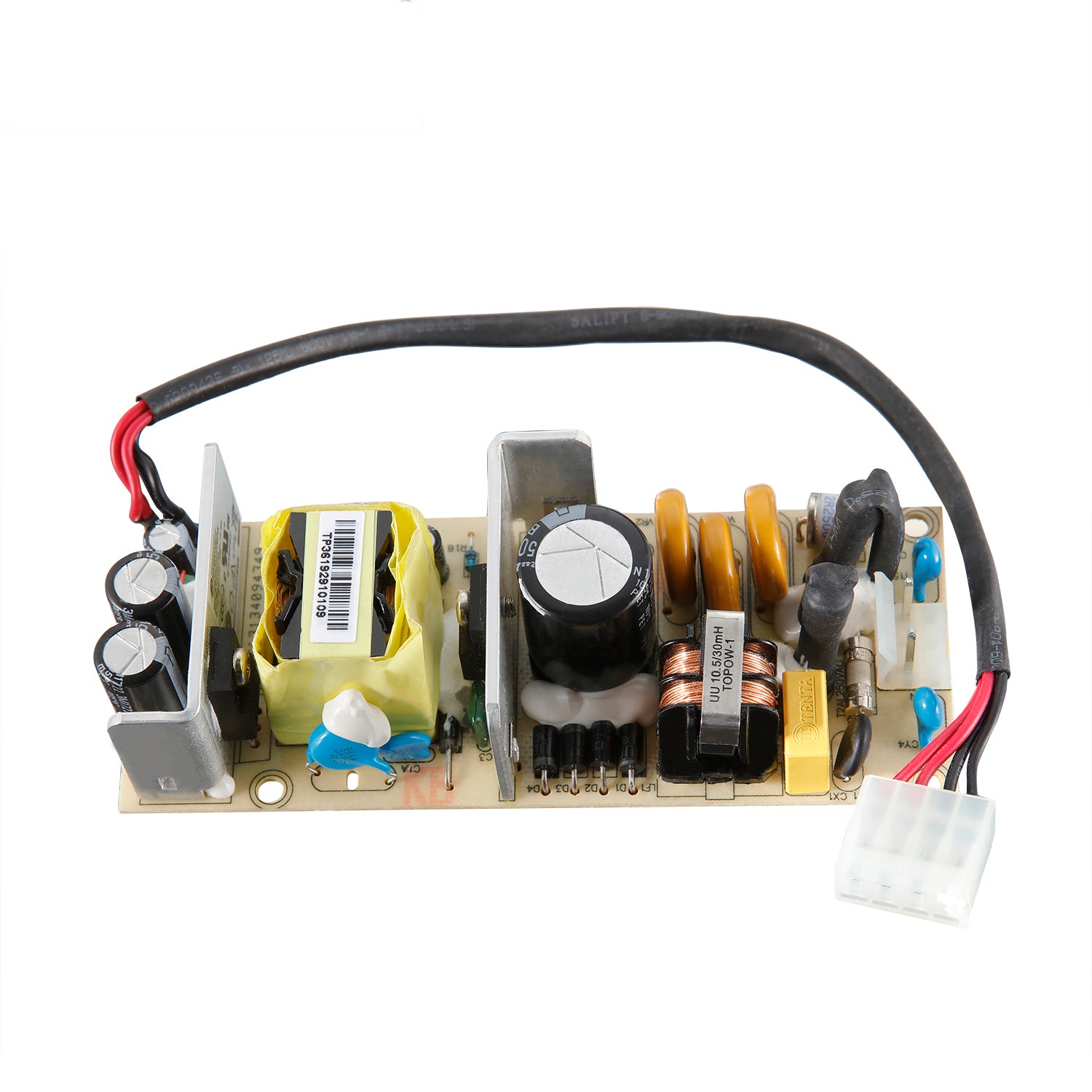
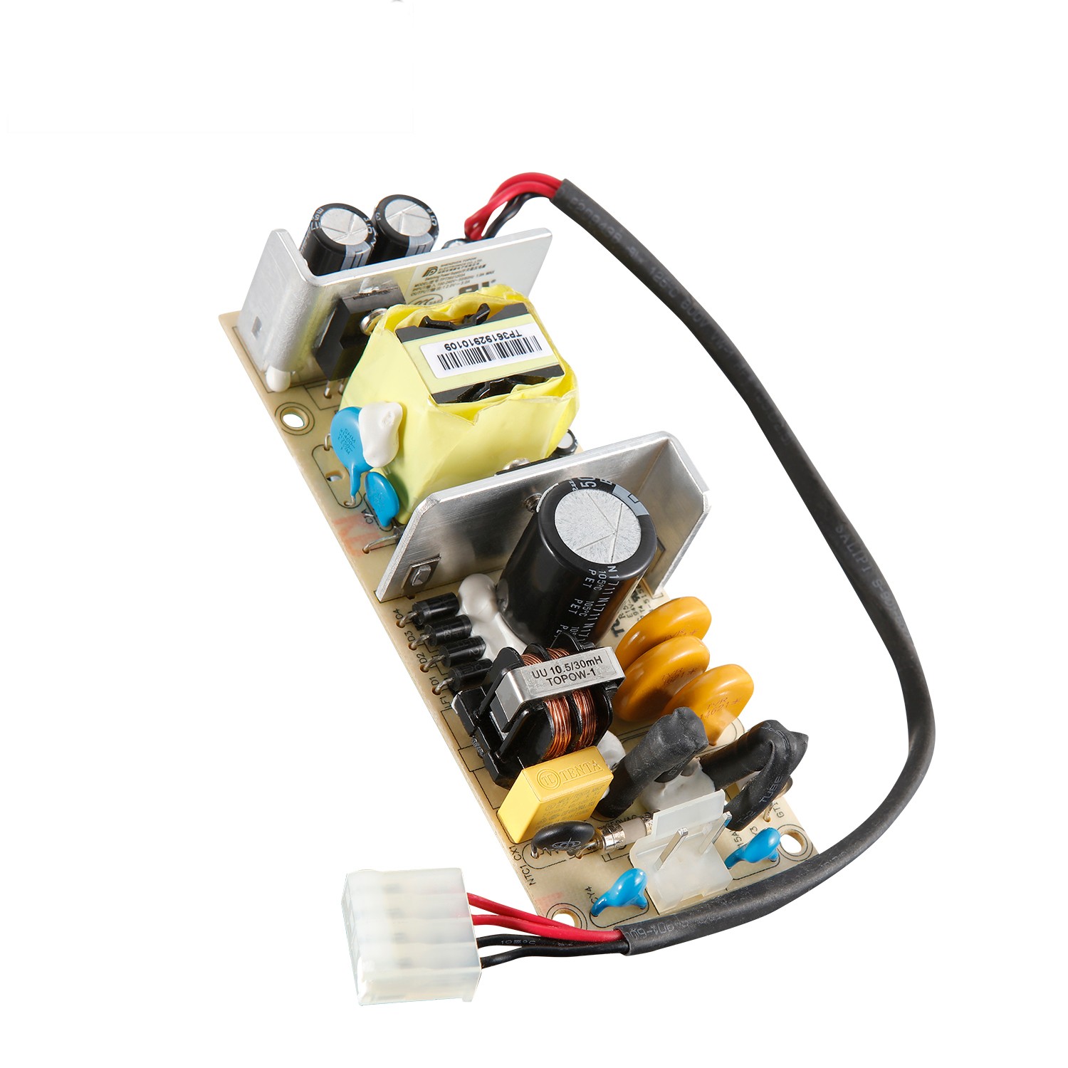
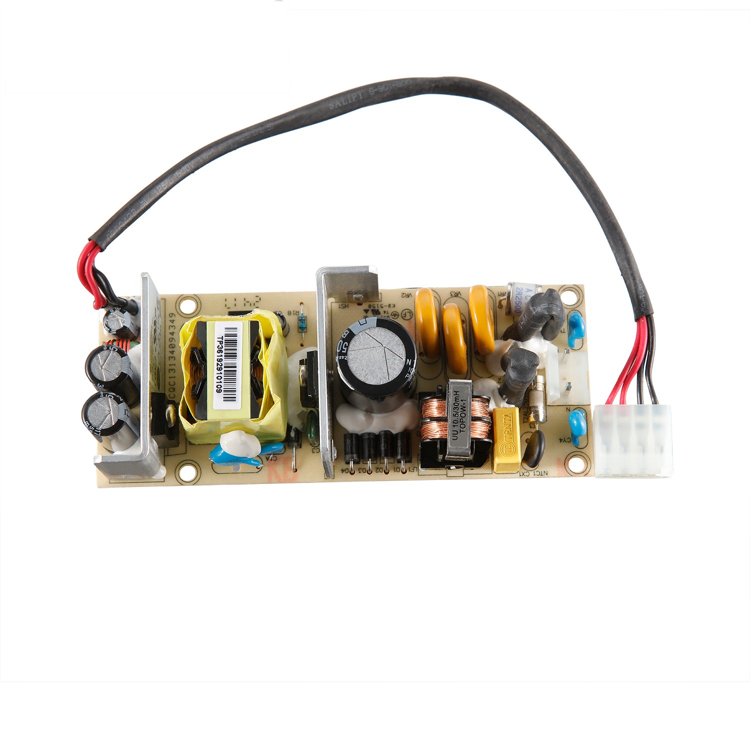
Pin Type: VH3.96 hollow

Output Power: 36W

Output Type (single or multiple?): Single 

Input Voltage: 90~264VAC

Input Frequency: 47~63Hz

Output Voltage: 12V

Output Voltage Accuracy: 0.05

Output Current: 3A

MTBF: At least 100,000 hours

Protection: OCP, SCP

Efficiency: >85% (220Vac input/rated output voltage, more than 50% of rated load current (heat engine for more than half an hour when testing efficiency)

Inrush Current: Cold start 230VAC/60A (MAX)

Working Temperature: -10~+55°C

Safety Certification: CCC, UL, CB

Packing: 0.12kg, 40pcs/6kg

Warranty Period: 2 Years


Product Detail

General rules:

This product is AC to DC power supply, 90~264V AC input, single output +12V, total output power 36W, through

CQC, TUV (CB) certification, in line with the EU RoHS directive.

1. Electrical characteristics

1.1 Input characteristics

1.1.1 Basic input characteristics

project

unit

Minimum

Typical value

Max

Remarks

AC input voltage range

Vac

90

110/220

264

The power supply is required to withstand long-term AC voltage input with an effective value of 300V without damage, and the test shall be accepted according to the 48-hour requirement;

Safety certification voltage

Vac  

100  

/

240


AC input voltage frequency

Hz

47

50/60

63


Input Current

A

/

/

1

90 Vac input, full load;

Inrush current

A

/

/

60   


230Vac/50Hz input, cold start at full load, normal temperature 25℃;


30            

110Vac/50Hz input, cold start at full load, normal temperature 25℃;

AC input system

/

/

Single phase input

/


1.1.2 Input protection features

project

unit

Minimum

Typical value

Max

Remarks

Input overcurrent protection

/

/

/

/

The AC input lines (L, N) have fuses

No input under or over voltage

Protection circuit

/

/

/

/

But it should meet the requirement that long-term input of 300V AC voltage is not damaged; AC input below 90VAC will not be damaged, and it can work normally after returning to the normal power grid.

1.2 Output characteristics

1.2.1 Basic output characteristics

project

unit

Minimum

Typical value

Max

Remarks

Output Power

W

/

36

/

90Vac~264Vac

Output voltage range

+12V

Vdc

11.4

12.0  

12.6


Output current range

+12V

A

0

/

3


Output efficiency

%    

85

/

/

220Vac input/rated output voltage, more than 50% of rated load current (heat engine for more than half an hour when testing efficiency)

Load loss

W

/

/

0.5


Stabilization accuracy

+12V

%

/

/

±5

Full voltage input range, full load output

Linear adjustment rate

%

/

/

±2

Rated 10%~100% load output, full voltage range change

Hello Elena

%

/

/

±3

Rated voltage input, 10%~100% load change

Noise + ripple

(Peak-to-peak value)

+12V

mV

/

/

120


It is carried out within the range of 90~300V input voltage and load, and the output terminal is tested with a 0.1µF ceramic or gold film capacitor and a 10µF electrolytic capacitor. The oscilloscope bandwidth is 20MHz, and the output ripple is <120mV

Dynamic response overshoot

%

/

/

±5

25%~50%~25% or 50%~75%~50% load change, current change rate 0.1A/µS, cycle 4mS;

Switch overshoot

%

/

/

±5


Power on time

S

/

/

3

T1≤3S, see Figure 1

Output rise time

mS

/

/

200

The output voltage rises from 10% to 90%,

T2≤200 mS

Power-down sustaining time

mS  

10

/

/

T3≥10mS

Power-down sustaining time

+12V

µF

/

/

3000

Rated input voltage, full load range test

Figure one
Bare panel low power 12v 3a variable adjustable switching power supply(图1)
1.2.2 Output protection features


project

unit   

Minimum

Typical value

Max

Remarks


Output overvoltage

Protection point

+12V

Vdc

14

  /

16

The power is not output and locked

Output overcurrent

Protection point

+12V

A

3.6

/

6

The power supply is in hiccup protection

Output short circuit protection

/

/

/

/

When the output terminal of the power supply is short-circuited to the ground, the power supply can be automatically protected; after the short-circuit is removed, the power supply can be automatically restored.


2. Environment

project

unit   

Minimum

Typical value

Max

Remarks

Operating temperature

-10

25

55


Storage temperature

-40

25

70

Stored at -40for 48 hours, the power supply can start normally

Working humidity

%

5

/

95

No condensation

Altitude

m

0

0

5000

High temperature derating under 3000~5000m operating environment conditions, the maximum working stability is reduced by 1℃ for every increase of 200m

Storage environment height

m

0

0

15250


3. Electromagnetic compatibility

ITEM

INDEX REQUIREMENTS

SDANDARD

Conducted interference (CE)

Level B

CISPR 22

Radiated interference (RE)

Level B  

CISPR 22

AC port (CS)

0.15~80MHz: 10V【80%AM(1kHz)】; (criterion A)

IEC61000-4-6

Radiation immunity (RS)

80~1000MHz: 10V/m【80%AM(1kHz)】;

1400~2700MHz: 10V/m【80%AM(1kHz)】 (criterion A)

IEC61000-4-3

Whole machine port ESD

Contact discharge: 6kV (level B); air discharge: 8kV (level B)

IEC61000-4-2

AC port EFT/B

Index: 2kV (criterion B)

IEC61000-4-4

AC port DIP

Drop to 0%, time 10ms; 0%, time 20ms; drop to 70%, time 500ms; drop to 0%, time 5000ms; (criterion B/B/B/C);

IEC61000-4-11

AC current harmonics

Rated voltage class A

IEC61000-3-2

AC voltage fluctuations,

Flashing

Pst value is not greater than 1;

Plt value is not greater than 0.65;

The relative voltage change dc does not exceed 3.3%;

The maximum relative voltage change dmax does not exceed 4%;

During the voltage change, the time when the d(t) value exceeds 3.3% is not more than 500ms.

IEC61000-3-3

Surge

Differential mode 6kV, 2 ohms; Common mode 6kV; 2 ohms, 1.2/50 (8/20) us mixed wave; Criterion ITU-B (Common mode 6KV is still required to remove common mode protection devices)

ITU-T K.44

electric shock

Differential mode ±3KA; common mode ±5KA, 8/20us waveform ITU-B

ITU-T K.44

4. Safety regulations

ITEM

 GRADE

STANDARD ( TEST CONDITIONS)

Input to output

3000Vac  

Lasts for 1 minute, no breakdown, no flashover phenomenon, leakage current <10mA (output is not grounded)

Input to ground

1500Vac   

Lasts for 1 minute, no breakdown, no flashover phenomenon, leakage current <10mA

Insulation resistance

50MΩ

Under normal temperature and pressure, the relative humidity is 90℅, and the test voltage is DC 500V, the insulation resistance of the AC part and the DC part of the main circuit of the rectifier to the ground, and the insulation resistance of the AC part to the DC part are not less than 50MΩ.

Leakage current  

Class I:≦3.5mA

Input 264VAC/50Hz.

5. Reliability

MTBF: 250,000 hours, working at 35°C ambient temperature and rated power grid and load.

E-CAP: 10 years, working at an ambient temperature of 25°C and rated power grid and load (with the complete chassis and fan).

HALT test:

sequence

Test items

Test Conditions

Analyzing conditions

1

HALT low temperature step stress test

The temperature of the sample starts from -10°C, and the temperature is reduced in steps of 10°C. The temperature point reached after stepping is called the temperature step; first, the test sample is powered off, the test box begins to cool down, and after reaching the set temperature of the test box, it stays 15-20 minutes to ensure that the inside of the chip is completely cold; power on the test sample, monitor the performance of the sample, and judge whether the startup is successful according to the performance indicators. Each temperature point should be tested for low temperature startup. The input voltage requirement for low temperature start is the highest and lowest input voltage, and the load is the maximum rated load. The residence time of each temperature step should be long enough (15-20 minutes after the product temperature reaches the temperature set point), so that the temperature of each device of the product is stable; at the same time, the predetermined test items (regulation accuracy, short-circuit function) should be completed , Switch machine test, communication function), and record data. During the temperature change process and after the functional test of each temperature step is completed, power-on and power-off must be performed at least 3 times. The input voltage of power-on and power-off is required to be the highest and lowest input voltage, and the load is the maximum output load. If the product fails and the temperature rises to the previous temperature step, it is judged whether the fault is the operating limit or the destruction limit; if it is determined to be the operating limit, the specific operating limit is precisely defined by using 5°C as the step length.

Failures that occur within -10°C must be corrected, and root causes must be analyzed for failures within [-10°C to -50°C]

2

HALT high temperature step stress test

The sample starts at 60°C, and the temperature rises step by step, and the step length is 10°C; the residence time of each temperature step should be long enough (15-20 minutes after the product temperature reaches the temperature set point), so that the temperature of each device of the product Stabilize; At the same time, it is guaranteed to complete the predetermined test items (regulation accuracy, short circuit function, switch machine test, communication function), and record the data. During the temperature change process and after the functional test of each temperature step is completed, power-on and power-off must be performed at least 3 times. The input voltage of power-on and power-off is required to be the highest and lowest input voltage, and the load is the maximum output load. If the product fails and the temperature drops to the previous temperature step, it is judged whether the failure is the operating limit or the destruction limit. If it is determined to be the operating limit, use 5°C as the step length to accurately define the specific operating limit.

Failures that occur within 110°C must be corrected, and root causes must be analyzed for failures within [110°C to 130°C]

3

HALT vibration step stress test

The initial vibration of the random vibration step test is 10 Grms, and the step length is 10 Grms. After it is greater than 30 Grms, the step length is adjusted to 5 Grms. Each vibration step stays for 15 minutes to ensure the completion of the predetermined test items (regulation accuracy, short circuit function, switch test, communication function), and record the data

Failures that occur within 30Grms of vibration must be corrected, and failures that occur outside of 30Grms must be analyzed for the root cause

4

HALT comprehensive stress test

Vibration limit value: the vibration operating limit found in the random vibration stepping test *90%;

High and low temperature range: [High and low temperature cycle low temperature point] = (low temperature operation limit-25°C) × 80% + 25°C;

【High temperature point of high and low temperature cycle】=(High temperature operation limit -25℃)×80%+25℃;

The test sample must fail. If two complete comprehensive stress test cycles are carried out and the test sample still has no failure, the test can be stopped.

Environmental test:

sequence

Test items

Test Conditions

Analyzing conditions

1

High temperature and humidity

Hot storage

The test box stays at 40°C (humidity between 90% and 95%) for 96h;

After the test, the material is not deformed, and the module should not be damaged or have abnormal performance (you can only check the default output voltage, voltage regulation accuracy, output ripple, and dynamic response).

2

Low temperature storage

test

Store at -40℃ for 24 hours;

After the test, the material is not deformed, and the module should not be damaged or have abnormal performance (you can only check the default output voltage, voltage regulation accuracy, output ripple, and dynamic response)

3

High temperature impact test (storage)

From 23°C to 70°C (humidity arbitrary), the rate of change is 30°C/h; 70°C stays at 72h (humidity arbitrary); 70°C drops to 23°C (humidity arbitrary), from 70°C to 23°C within 5 minutes;

After the test, the material is not deformed, and the module should not be damaged or have abnormal performance (you can only check the default output voltage, voltage regulation accuracy, output ripple, and dynamic response).

4

Low temperature impact test (storage)

Decrease from 23°C to -40°C (humidity arbitrary), the rate of change is 30°C/h; stay at -40°C for 72h (humidity arbitrary);

-40℃ to 23℃ (humidity arbitrary), from -40℃ to 23℃ within 5min;

After the test, the material is not deformed, and the module should not be damaged or have abnormal performance (you can only check the default output voltage, voltage regulation accuracy, output ripple, and dynamic response)

5

High and low temperature cycle

Ring (storage)

70°C down to -40°C (humidity arbitrary), the rate of change is 60°C/h; storage for 24 hours;

After the test, the material is not deformed, and the module should not be damaged or have abnormal performance (you can only check the default output voltage, voltage regulation accuracy, output ripple, and dynamic response)

6

High temperature work test

AC input 90V, rated load, ambient temperature 55℃, 12H;

AC input 300V, rated load, ambient temperature 55℃, 12H;

After the test, there is no deformation of the material, and the module should not be damaged or have abnormal performance.

7

Low temperature work

test

AC input 90V, rated load, ambient temperature -10℃, 12H;

AC input 300V, rated load, ambient temperature -10℃, 12H;

After the test, there is no deformation of the material, and the module should not be damaged or have abnormal performance.

8

Alternating damp heat

Test

Made)

25℃~40℃(indoor)/25℃~55℃(outdoor), 95%RH, after 48h test, it should not be damaged

After the test, the material is not deformed, and the module should not be damaged or have abnormal performance (you can only check the default output voltage, voltage regulation accuracy, output ripple, and dynamic response)

9

High and low temperature cycle

Ring test

(jobs)

fulfill the standard

GB/T 2423.22-200

After the test, the material is not deformed, and the module should not be damaged or have abnormal performance (you can only check the default output voltage, voltage regulation accuracy, output ripple, and dynamic response).

10

High temperature aging

High temperature current limiting operation for 24 hours

Electromagnetic devices, especially transformers/inductors, should not have scorching or abnormal colors, capacitors should not have violent valves, bulging, etc., and the power supply performance should not be degraded

11

Vibration test

The frequency is 10~55Hz, the acceleration is 50m/s2, and the X, Y, and Z directions are in turn for 30min vibration

The module should be free from mechanical damage, disconnection, component falling off, etc., and all indicators should be normal.

Limit test:

sequence

Test items

Test Conditions

Analyzing conditions

1

Output current limit

Run 2Hrs under the condition before current limit protection

The prototype is not damaged, and it should be able to automatically resume normal operation after troubleshooting

2

Input current limit

Run 2Hrs before current limit protection and undervoltage protection

The prototype is not damaged, and it should be able to automatically resume normal operation after troubleshooting

3

Input voltage jump, and output dynamic load test

Adjust the input voltage to jump between the lower limit of the input voltage (duration is 1S) and the upper limit of the input voltage (duration is 1S), and the output is adjusted between the maximum load (duration of 1mS) and no load (duration of 1mS) Inter-jumping, the rate of change is defined by specifications, and it runs for 2 hours. Observe the output voltage of the power supply.

The power supply can run stably without damage or other abnormal phenomena, and the output voltage is within the specifications

4

Long-term short circuit test

Short-circuit for 2 hours, short-circuit with wire, test time is 2Hrs

The power supply is not damaged, the module should be able to protect; after troubleshooting, it should be able to automatically resume normal operation

5

Input switch machine repeatedly

Switch the power supply repeatedly at the upper and lower limits of the input voltage and full load conditions, turn on for 3 seconds, turn off for 1 second, and switch 1000 times  

The machine can be turned on and off normally without abnormal conditions

6

Static high voltage input

Input 318V, output full load, continuous operation for 48 hours

The power supply can run stably without abnormal conditions

7

High voltage input test

Steady-state high voltage, start the test from 300Vac, Step is 10V, and the duration of each step is 30min, until the power module fails, record the voltage at this time

Record the voltage when the power supply fails

8

AC special waveform test

AC input special waveform superposition test  

The power supply can run stably without abnormal conditions

9

Input undervoltage point cycle test

AC overvoltage and undervoltage, DC no-load to overcurrent point cyclic operation 2Hrs

The prototype is not damaged, and it should be able to automatically resume normal operation after troubleshooting

6. Special requirements

6.1 The material of the PCB board is CEM-1 single-sided board.

6.2 The input large capacitor (bit number C1) adopts 450V withstand voltage.

6.3 AC input terminal: AC input is an AC standard 2PIN terminal, and it is required to be located on the power board.

6.4 DC output: DC output cable is required to be soldered directly on the power board, and the other end is a DC power connector.

6.5 Withstand voltage test

Test conditions: L+N short-connected pair secondary (including output and signal terminals) test withstand voltage value 3KV; L+N short-connected pair

Protected area 1.5kv.

①: During the test, the withstand voltage equipment does not alarm;

②: The gas discharge tube must be disconnected when the leakage current does not exceed 10mA;

f. ATE test: ATE, the conventional performance test of the unit needs to be fully covered

g. ORT test: ORT, 168 hours, 1/1000 sampling, temperature and aging are the same

h. Lightning strike test: lightning strike, 3PCS each time, once every 3 months, test according to the required indicators;

i. Surge sampling test: Surge sampling test, 3PCS each time, once every 3 months, test according to the required indicators;

j. The power supply products need to be affixed with bar codes for traceability;

7. Appearance structure

7.1 Power supply size

115mm (length) * 46mm (width), tolerance is ±0.5mm; the height of tin surface pins and SMD components is controlled within 3mm

Inside, the height of all components on the PCB board (including the PCB board) is limited to 29mm.

As shown below:

Bare panel low power 12v 3a variable adjustable switching power supply(图2)

7.2 Output wiring diagram (see attachment)

7.3 Input terminal block

Bare panel low power 12v 3a variable adjustable switching power supply(图3)

7.4 Appearance of main power supply components

The following is the appearance of the power supply (refer to the schematic diagram), and the main components may be used alternately. Note that the dispensing process is subject to the actual product.

Bare panel low power 12v 3a variable adjustable switching power supply(图4)  Bare panel low power 12v 3a variable adjustable switching power supply(图5)
8. Circuit diagram
Bare panel low power 12v 3a variable adjustable switching power supply(图6)
9. PCB diagram
Bare panel low power 12v 3a variable adjustable switching power supply(图7)
Bare panel low power 12v 3a variable adjustable switching power supply(图8)
Bare panel low power 12v 3a variable adjustable switching power supply(图9)

10. Packaging

10.1 Net weight of power supply: 128 grams. (Excluding packaging materials, weight deviation ±10%)

10.2 Packing drawing

Bare panel low power 12v 3a variable adjustable switching power supply(图10)
10.3 Loading and transportation experiment

Pilot projects

Test parameters

judgement standard

Random vibration

Fixed frequency test conditions: vibration amplitude: 4.5mm, vibration frequency: 35HZ, vibration time 30 minutes.

Sweep frequency test conditions: Vibration frequency: 10-50HZ, vibration time 30 minutes.

There should be no mechanical damage, disconnection, falling off of components, etc. in the test of the fixed housing of the module, and all indicators should be normal.

fall

Surface, corner, edge drop:

Drop height: 100cm

Drop 1 corner, 3 edges and 6 faces each once

The packaged module should be free of mechanical damage, wire breakage, or parts falling off, etc., and all indicators should be normal.

11. Name tags and barcodes
Bare panel low power 12v 3a variable adjustable switching power supply(图11)
12. Safety certificate (see attachment)