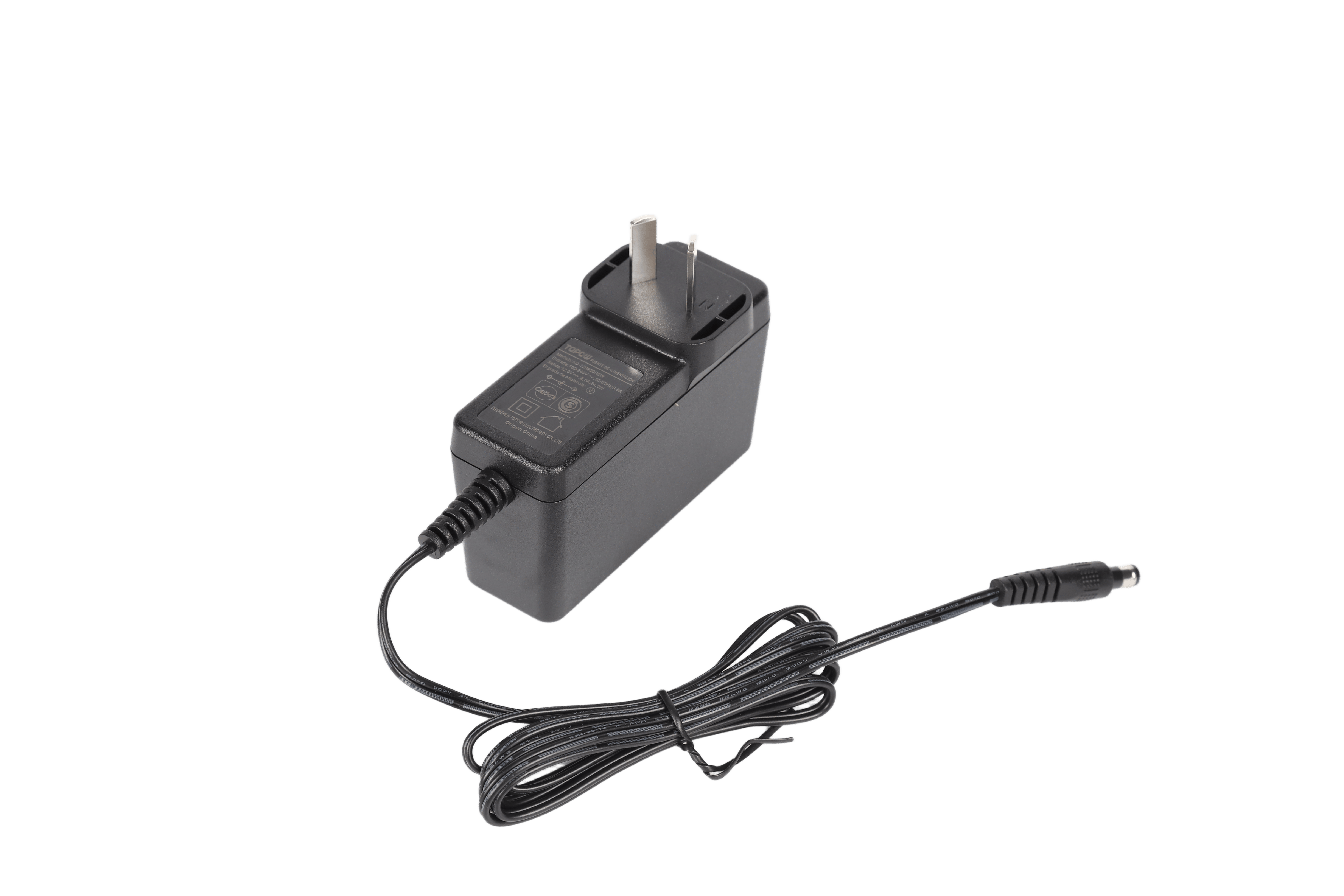
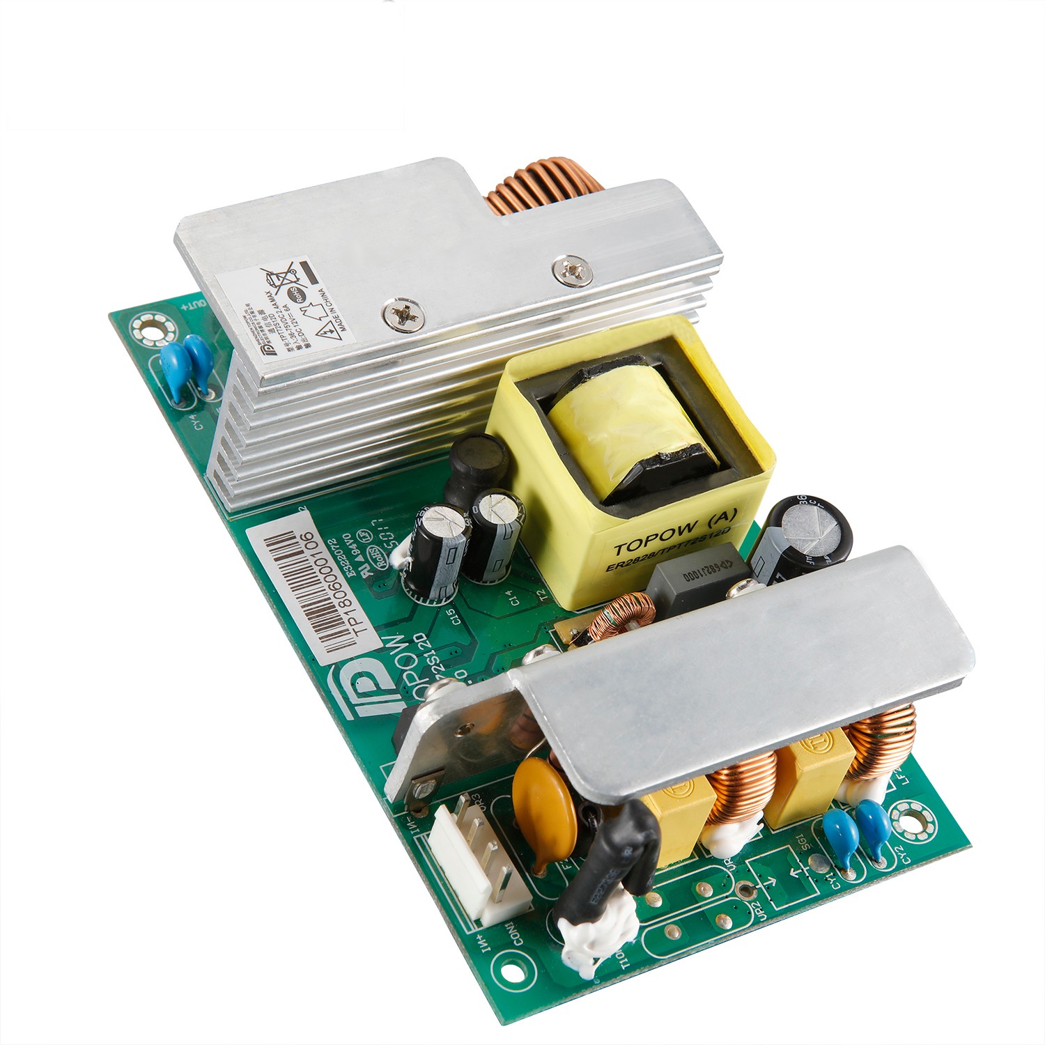
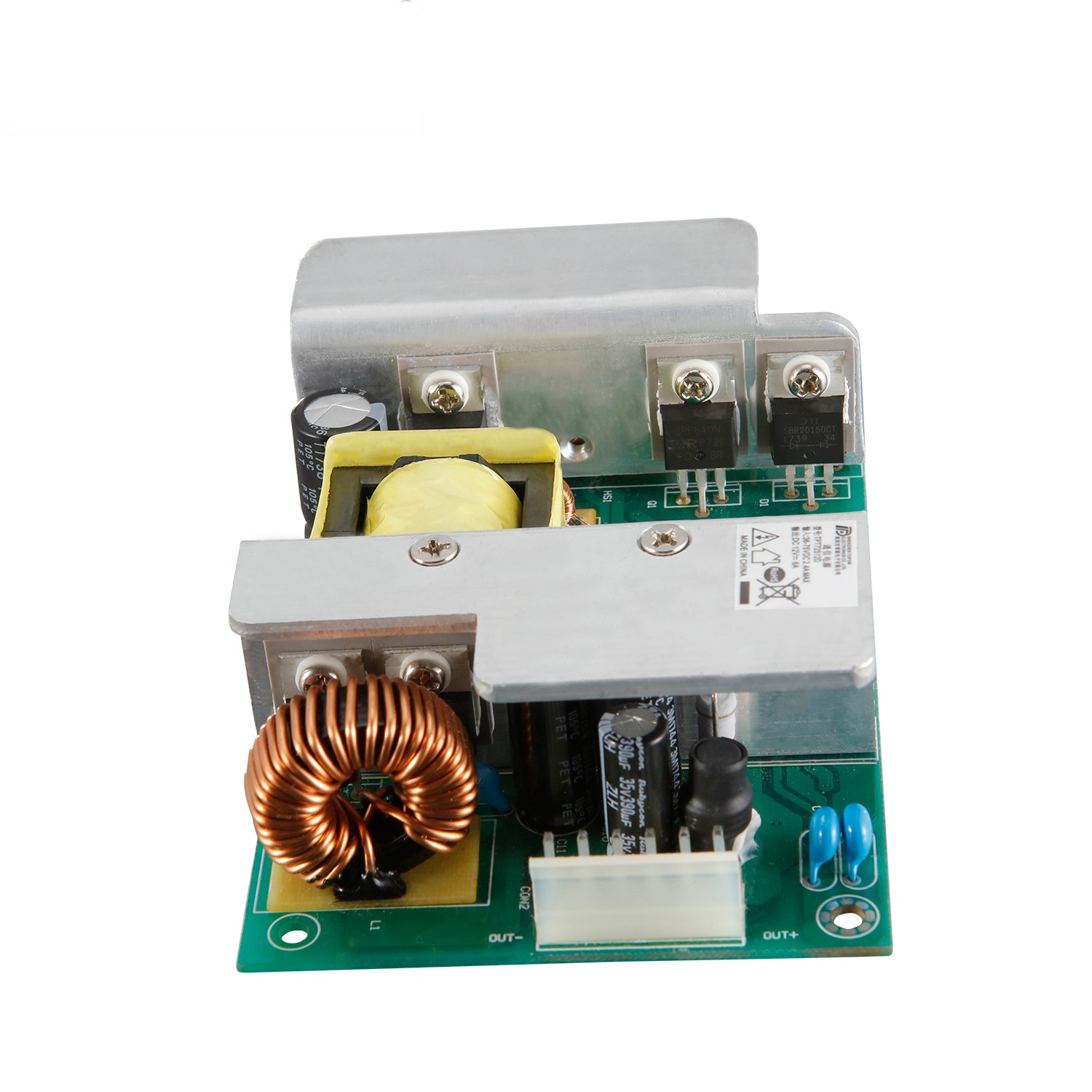
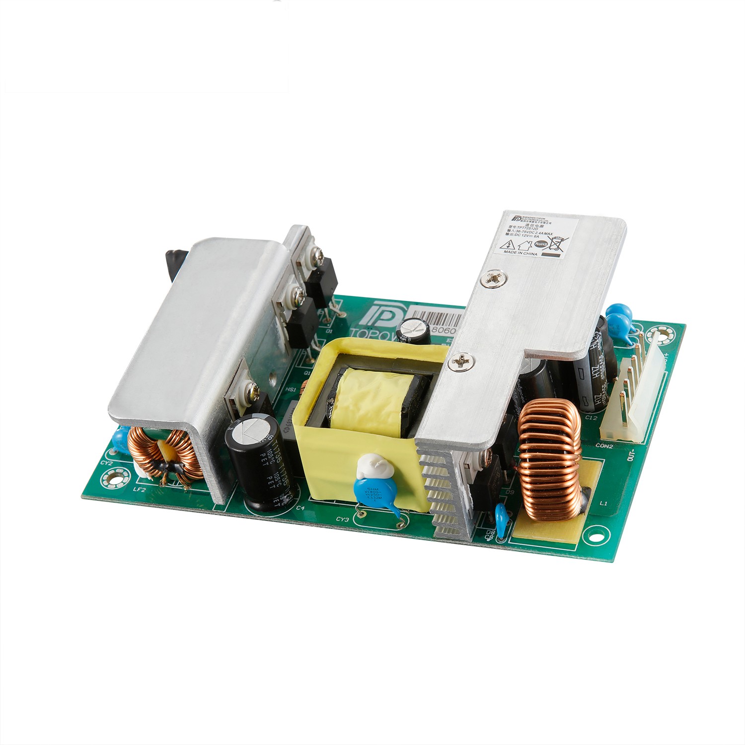
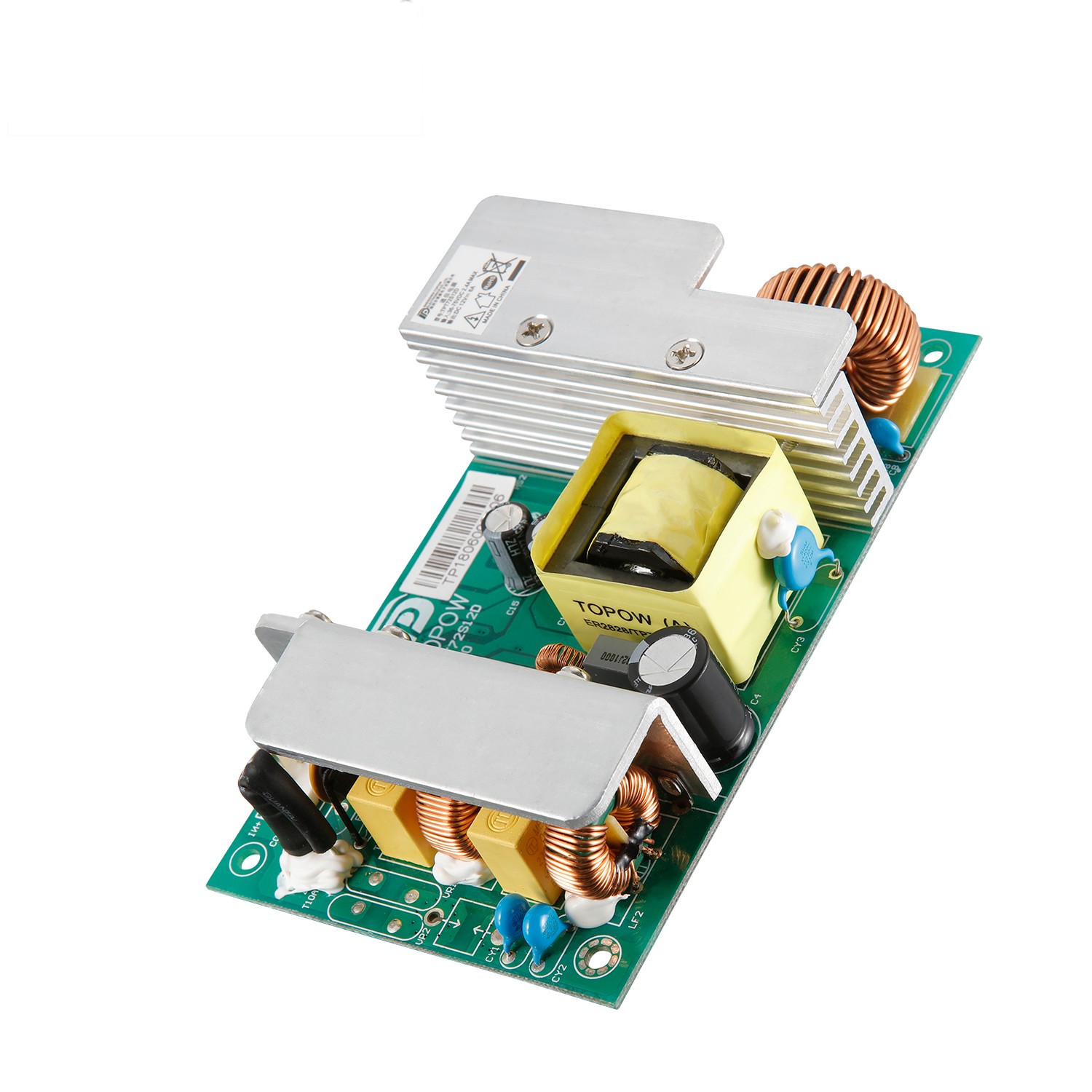
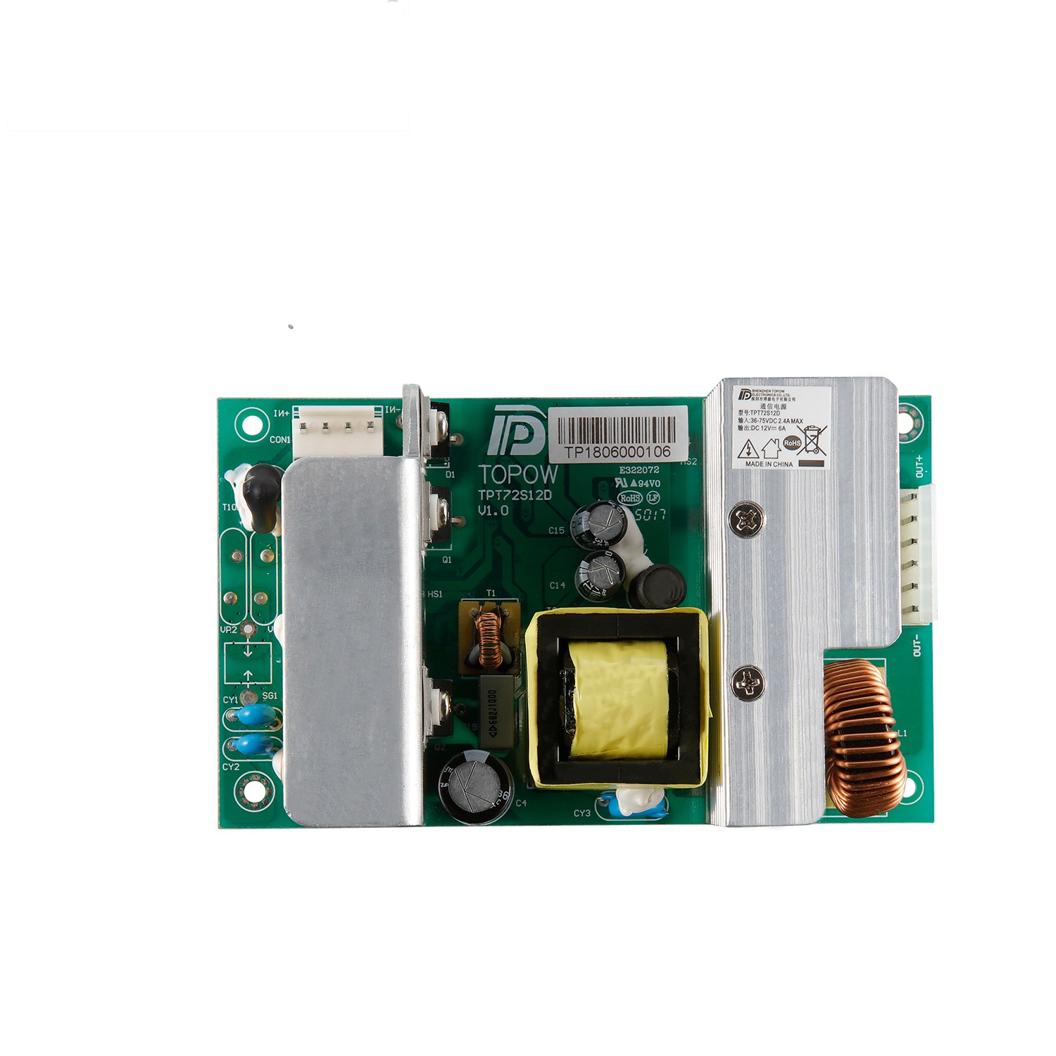
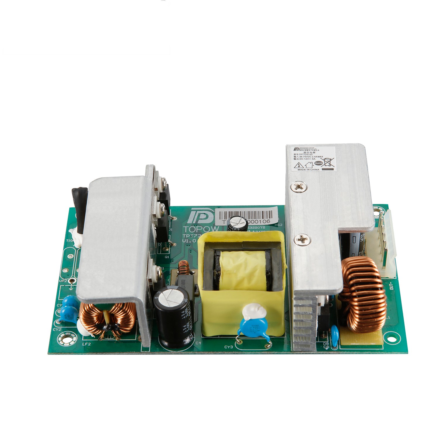
Product

>
<

24 months warranty power supply 36 ~ 75VDC dc power supply

TPT72S12D

General

1    Input Characteristics

2    Output Characteristics

3    Protection

4    Leakage Current

5    Safety Approval

6    Hi-Pot

7    Environment 

8    Vibration

9    MTBF

10   Label specification

11   Mechanical

12   Appearance

13   Package

14   SCH&PCB

15   Bill of materials


Product Detail

1. POWER SUPPLY OVERVIEW:

1.1 INPUT ELECTRICAL CHARACTERISTICS OVERVIEW

1.1.1 Input voltage range: 36Vdc to 75Vdc

1.1.2 Nominal input Normal voltage range: 48Vdc

1.1.3 Standby power Loss: measured at 36V—75V No load

1.1.4 Max input dc current:2.4Amax at full load condition @36VDC~75VDC INPUT

1.1.5 Inrush current: 36VDC and75VDC test condition (Cold start), Full load and CC mode, Fuse can’t break

1.1.6 Input Power (W): 86W(max)@Full Load

1.1.7 Efficiency: 84%(min) at 48Vdc, full load condition;

1.1.8 Leakage Current: Less Than 3.5mA(max), 48Vdc input

1.1.9 Input Fuse: T10A/250Vac, T6.3A/250Vac

1.1.10 Operating frequency: 80KHz

1.2 OUTPUT ELECTRICAL CHARACTERISTICS OVERVIEW

1.2.1 OUTPUT VOLTAGE RANGE

Output Voltage

Min value

Normal value

Max value

Requirements

Vout

11.4V

12V

12.6V

Vin=36Vdc75Vdc

      Io=6A

Maximum Output Capacitance 2000uF

1.2.2 OUTPUT CURRENT RANGE

Output Current

Min value

Normal value

Max value

Requirements

Iout

0A

6A

6A

Vin=36Vdc75Vdc

Note: Iout =0A, Criterion: No damage, hazardous, and resonance

1.2.3 LINE REGULATION

Line Regulation

Min value

Normal value

Max value

Requirements

Vout: 12V

/

±1%

/

Vin=36Vdc75Vdc

Io=6A

1.2.4 LOAD REGULATION

Load Regulation

Min value

Normal value

Max value

Requirements

Vout: 12V

/

±2%

/

Vin=36Vdc75Vdc

 Io=6A

1.2.5 OUTPUT VOLTAGE TOLERANCE

Output voltage tolerance

Min value

Normal value

Max value

Requirements

Vout: 12V

/

±2%

    /

Vin=36Vdc75Vdc Io=6A

1.2.6 OUTPUT RIPPLE & NOISE

Output Voltage

Ripple & Noise (Max.)

Vout: 12V

1. Ripple: 120mVp-p(max)@12Vdc

2. RMS: 30mV(max)@12Vdc

Note: 1) Measurements shall be made with an oscilloscope with 20MHz bandwidth.

2) Outputs shall be bypassed at the connector with a 0.1Uf ceramic capacitor and a 10Uf electrolytic capacitor to simulate system loading.

1.2.7 OUTPUT TRANSIENT RESPONSE

Voltage regulation

Slew Rate

Test Condition: Load Changing Scope

12V ±5%;

3A/us

1% to 50% load and 50% to 100% load

1% to 100% load

1.2.8 OUTPUT OVERSHOOT / UNDERSHOOT

Output

Overshoot / Undershoot

Min value

Normal value

Max value

Requirements

Vout: 12V

/

/

±5%

Iout=0A-6A

turn-on and turn-off

1.2.9 TURN ON TIME

Turn on time

Min value

Normal value

Max value

Requirements

Vout: 12V

/

/

3sMeasured

Vin=48Vdc

Io=6A

1.2.10 OUTPUT HOLD TIME

Output Hold Time

Min value

Normal value

Max value

Requirements

Vout: 12V

3mS

/

/

Vin=48Vdc  Io=6A

1.2.11 OUTPUT RISE TIME

output Rise time

Min value

Normal value

Max value

Requirements

Vout: 12V

/

/

30mS

Vo=10%-90% Io=6A

1.3 Protection function

1.3.1 Output overcurrent protection

Output over current Protection

Min value

Normal value

Max value

Requirements

Vout: 12V

7.8A

/

12A

Hiccup  Auto-recovery mode

1.3.2 OUTPUT SHORT CIRCUIT PROTECTION.

Output Short Circuit Protection 

Comments


Hiccup  Auto-recovery mode

1.3.3 OUTPUT OVER VOLTAGE PROTECTION

over voltage Protection

Min value

Normal value

Max value

Requirements


Vout: 12V


15V


/


18V


Locked, can be restored after the fault is removed and restarted

1.3.4 INPUT UNDER VOLTAGE PROTECTION


Input under voltage Protection


1. Turn-On Voltage Threshold (32~35VDC)

2. Turn-Off Voltage Threshold (30~33VDC)

3. Lockout Hysteresis Voltage

(1~3VDC)


Locked, can be restored after the fault is removed and restarted

2. Insulation performance

2.1 Insulation resistance

Requirements

Parameter value

Note

500VDC/25/70%RH

100MΩ

I/P-O/P,I/P-FG,O/P-FG

2.2 ISOLATION WITHSTANDING VOLTAGE

Parameter name

Parameter value

Note

Input To Output

1500Vac/10mA/1min 

No breakdown or flashover phenomenon

Input To PG

1500Vac/10mA/1min

No breakdown or flashover phenomenon

Output To PG

500Vac/10mA/1min

No breakdown or flashover phenomenon

3. Safety requirements:

1. CB Report IEC 60950-1:2005 (Second Edition) + Am 1:2009 + Am 2:2013

2. UL Report (request on future demand) UL 60950-1, 2nd Edition / CSA C22.2 No. 60950-1-07, 2nd Edition

3. TUV Report (request on future demand) EN 60950-1:2006/A12:2011

4. Fire Class- no fan (Including DC input connector) 94V-0

4. Electromagnetic compatibility EMC

4.1 Electromagnetic interference EMI

The electromagnetic interference of the power supply meets the following rules:

The power supply shall comply with the following Criterion:

1) Conduction Emission: EN 55022:2010+AC:2011 Class B

2) Radiated Emission: EN 55022:2010+AC:2011 Class B

4.2 Electromagnetic immunity EMS

The electromagnetic immunity of the power supply meets the following rules:

The power supply shall comply with the following Criterion:

1) Electrostatic immunity ESD: IEC61000-4-2:2008 (criterion B), air discharge 8kv, contact discharge 6kv

2) Burst anti-interference EFT: IEC61000-4-4:2012, Test level: 1kV Min Criterion:B

3) Lightning surge Surge:

IEC61000-4-5:2005

Test level (1.2/50 Waveform)

1. Positive to GND: 0.5KV

2. Negative to GND: 0.5KV

Min Criterion :B

 4) Voltage Dips: *IEC61000-4-29.

 5) Radiation immunity RS: *IEC61000-4-3:2006+A1:2007+A2:2010, Test level: 3V/m Min Criterion:A

 6) Conducted immunity CS: *IEC61000-4-6:2008, Test level: 3V Min Criterion:A

 7) Power frequency magnetic field immunity PMF: *IEC61000-4-8:2009, Test level: 1 A/m Min Criterion:A

5. Working environment

5.1 Products (E-CAP) life calculation MTBF

Lx=Lo*2^((To-Tx)/10) @ 50℃ 5 Year (Over 44000 hours)

(Using Japan’s capacitor, All capacitor to use specification at 105°C)

5.2 Ambient temperature

5.2.1 Operating temperature: -10℃ to +50℃. Note: Temperature coefficient 0.05%/ ℃ (max) 5.2.2 Storage temperature Store: -40℃ to +85℃.

5.2.3 The derating curve is as follows:

24 months warranty power supply 36 ~ 75VDC dc power supply(图1)

5.3 Ambient humidity

5.3.1 Operating: From 5%to90% relative humidity (non-condensing).

5.3.2 Store: From 5% to 95% relative humidity (non-condensing).

5.4 Altitude

5.4.1 Operating: 0 to10,000 ft.

5.4.2 Store:0 to 20,000ft.

5.5 Cooling method:

Natural cooling.

5.6 Vibration test

1. Test Conditions: ETSI EN 300 019-2-3 T3.2 and IEC 60068-2-64

(1) Operating Vibration:

<1> 5 ~ 10 Hz (+12 dB/Oct)

<2> 10 ~ 50 Hz, ASD 0.02 m2/s3

<3> 50 ~ 100 Hz (-12 dB/Oct)

<4> Axes of Vibration: 3 axes

<5> Test Duration: 30 minutes / axis

(2) Non-Operating Vibration:

<1> ASD: 0.01 G2/Hz

<2> Frequency: 20 ~ 500 Hz

<3> Direction: X, Y, Z Axes

<4> Test Duration: 30 minutes / axis

5.7 Impact test

196.1m/s²(20G),11ms, once each X, Y and Z axis.

5.8 Drop test

Accroding to IEC 60068-2-31 test Program

24 months warranty power supply 36 ~ 75VDC dc power supply(图2)

6. Connector pin definition PIN CONNECTION

7.1.Pin-CON1 DC Connection And Function TYPE: vertical 3.96.0MM*4PIN

NO

Pin Connection

Function

1

IN-

INPUT-

2

IN-

INPUT-

3

      IN+

               INPUT+

4

IN+

INPUT+

7.2.Pin-CON2 Connection And Function TYPE: 3.96MM*6PIN

NO

Pin Connection

Function

1

GND

RETURN

2

GND

RETURN

3

GND

RETURN

4

+12V

12V OUTPUT

5

+12V

12V OUTPUT

6

+12V

12V OUTPUT

7. Block schematic diagram
24 months warranty power supply 36 ~ 75VDC dc power supply(图3)
8. Chart(Unit: mm)
24 months warranty power supply 36 ~ 75VDC dc power supply(图4)