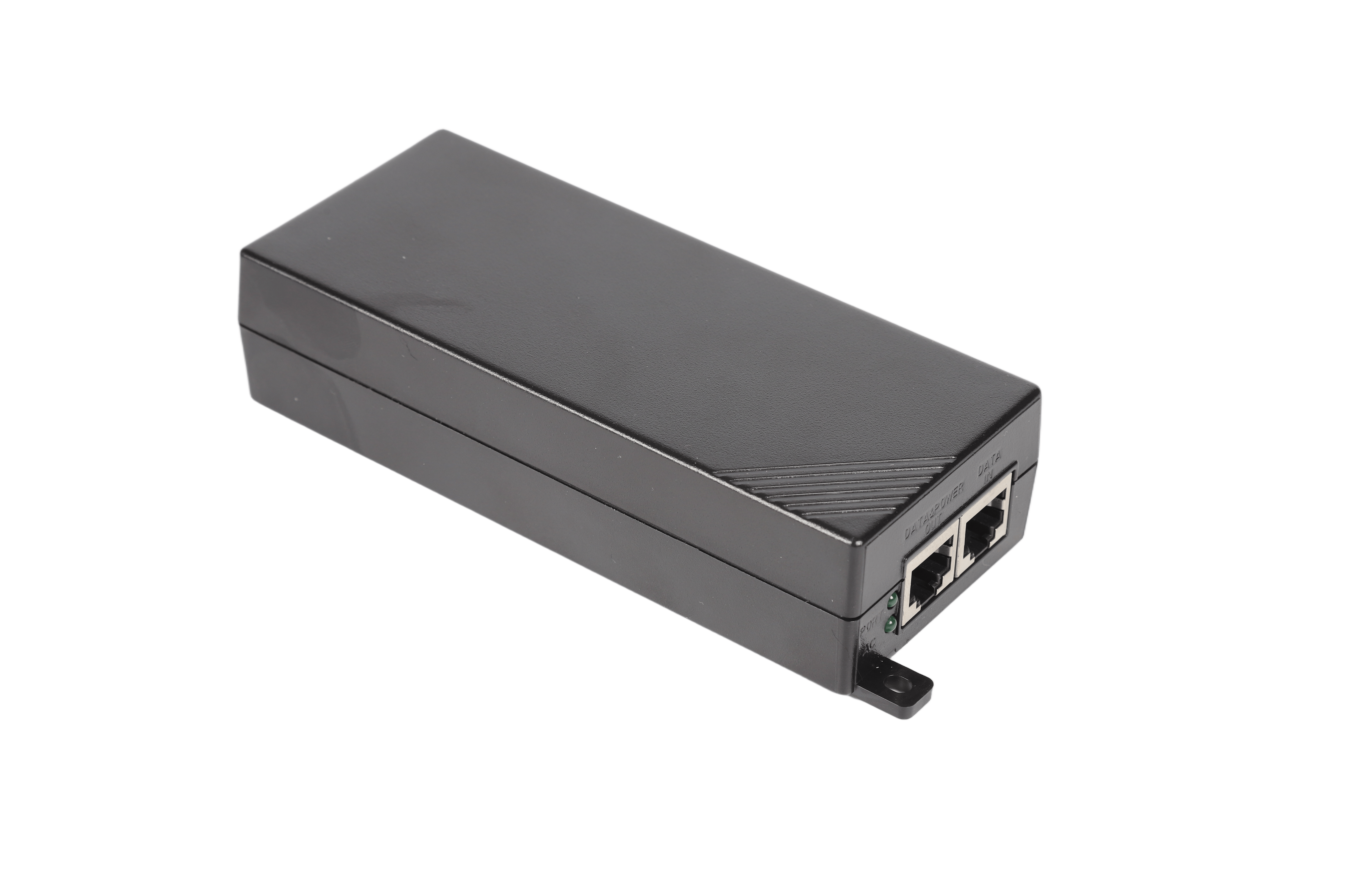
Product

>
<

New ABS Fire Shell Gigabit ESD Protection POE Powered Adapter Power Supply 90W POE Injector

TPT90S56POE

Color: Black

Output Power: 90W

Input Voltage: 90~264VAC

Input Frequency: 47~63Hz

Output Voltage: 56V

Output Voltage Accuracy: 0.05

Output Current: 1.6A

MTBF: At least 100,000 hours

Protection: OCP, SCP

Efficiency: >90%

Inrush Current: Cold start 230VAC/80A (MAX)

Working Temperature: -10~+50°C

Safety Certification: CE, FCC

Warranty Period: 2 Years


Product Detail

1 Overview

This specification specifies the detailed specifications of the 90W (55.5V/1.62A) custom power adapter designed and developed by our company.

2 function description

PoE network port output desktop adapter is the integration of AC/DC power supply and PSE, 90Vac~290Vac input, working temperature

The range is -40℃ to 65℃, natural heat dissipation, support rated 55.5V/90W rated output, with AC and PORT indicator design. The power supply has input under-voltage protection, output over-current protection, output over-voltage protection, output short-circuit protection and other functions, meets the application requirements in the IEEE802.3bt standard, and is compatible with IEEE802.3af and IEEE802.3at standards, and the average output efficiency meets 85 %.

3Use environment

Table 1 Environmental Specifications Table


Project

Unit

Minimum

Typical value

Max

Remarks

Operating temperature

-40

25

65

1. CCC report certified 65temperature

2. CB report, UL report certification 50

-40 degrees require 5 minutes to start and normal output voltage.

Storage temperature

-40

25

70


Relative humidity

%

5

/

95

No condensation

Altitude

m

-60

/

5000

Under the operating conditions of 1800~5000m, the operating temperature will decrease by 1ºC for every increase of 220m; the low temperature of -40will not decrease with the altitude

working pressure

kPa

53

/

106


Salt spray requirements

/

/

/

/

Remarks: In the B1 environment, the input AC port, output network port and other structural parts need to be tested in salt spray.


4 Electrical characteristics

4.1 Input characteristics

4.1.1 Basic input characteristics

Table 2 Input the basic characteristics table

Project

Unit

Minimum

Typical value

Max

Remarks

Rated input voltage range

Vac

100

110/220

240


Input voltage range

Vac

90

110/220

290

Input 318VAC high voltage is not damaged, 4 hours acceptance

AC input voltage frequency

Hz

47

50/60

63


Input impulse current

A

/

/

60A

Start cold state, input 264VAC; meet the standard requirements: ETSI300132-3

AC input system

/

/

Single phase input

/

Single phase input

AC input interface

/

/

/

/

C14 input socket

New ABS Fire Shell Gigabit ESD Protection POE Powered Adapter Power Supply 90W POE Injector(图1)
 Impulse current ETSI300132-3 standard diagram

4.1.2 Input protection features

Table 3 Input protection characteristics


Project

Unit

Minimum

Typical value

Max

Remarks

Input undervoltage protection point

Vac

/

/

85

Self-recoverable, long-term input undervoltage is not damaged

Input undervoltage recovery point

Vac

/

/

90

Backlash ≥5Vac

Input overcurrent protection

/

/

/

/

There is a fuse at the AC input, and the main circuit fuse and protective fuse are required to be designed separately.

Insurance placement diagram:
Remarks:

Disable fuse resistor

Y capacitor

pf

/

/

500

The equivalent capacitance across the primary and secondary side is less than 500pF


4.2 Output characteristics

4.2.1 Basic output characteristics

Table 4 Output basic characteristics table

Project

Unit

Minimum

Typical value

Max

Remarks

Rated output power

W

/

90

/

90~290Vac full range input

Output voltage range

Vdc

54

55.5

57

Full voltage input range, full load output

Meet IEEE802.3bt standard PoE

Output efficiency

%

85

/

/

Rated input voltage, load coverage 25%, 50%, 75%, 100%, average efficiency 85%

Source adjustment rate

%

/

/

±2

Rated current output, full voltage range change

Hello Elena

%

/

/

±3

Rated voltage input, full load change

Noise + ripple

(Peak-to-peak value)

mV

/

/

200

It is carried out within the full input voltage and load range, and a 0.1uF ceramic or gold film capacitor and a 10uF electrolytic capacitor are connected to the output terminal during the test. The bandwidth of the oscilloscope is 20MHz

Dynamic response overshoot

%

/

/

±5

25%~50%~25% or 50%~75%~50% load change, current change rate 0.1A/us, cycle 4ms.

Dynamic response recovery time

us

/

/

500

25%~50%~25% or 50%~75%~50% load change, current change rate 0.1A/us, cycle 4ms

Switch overshoot

%

/

/

±5

Full voltage input range, full load output

Output voltage rise time

ms

/

/

200

The output voltage rises from 10% to 90%, and the rated load is tested before the PSE chip. The PSE chip meets the IEEE802.3 af/at/bt standard. The low-temperature -40°C startup waveform does not require smoothness, but multiple restarts are not allowed.

Boot delay time

s

/

/

5

The time from AC input to PSE input voltage settling to 90% Vout.

The low-temperature -40°C startup waveform does not require smoothness, but multiple restarts are not allowed.

Shutdown hold time

mS

20

/

/

Meet the DIP requirements in the EMC list

PoE handshake time

S

/

/

5

After the PSE input voltage is 100% established, the PD device is reliably inserted into the PoE port to the time that the PoE port voltage is established to 100% Vout); the PD device connected to the PoE port can be grounded or ungrounded.

Temperature Coefficient

%/

/

/

±0.02

Rated output voltage and output current, full range of operating temperature.

Capacitive load

uF

47

/

1000

Capacitive load refers to the capacitance value of the capacitor on the single board of the PD device. After the PSE voltage is established, the slow-start MOS tube is turned on, and the PD chip controls the current limit to charge the capacitor. This specification can only be tested and accepted on the whole device. No PD board, no acceptance is required.

4.2.2 Output protection features

Table 5 Output protection characteristics table

Project

Unit

Minimum

Typical value

Max

Remarks

Output overvoltage protection point

Vdc

/

/

60

Hiccup protection mode, no damage; meet the ES1 standard of IEC62368-1.

Output overcurrent protection point

A

1.75

/

2.2

The hiccup protection mode meets the requirements of the IEEE802.3bt standard.

Output short circuit protection

/

/

/

/

Long-term short-circuit, self-recovery after the short-circuit fault is eliminated, meeting the requirements of IEEE802.3bt standard.

4.3 Indicator requirements

Table 6 Power adapter indicator requirements

Indicator

colour

Illuminance

status

PORT port indicator

green

/

PoE connection status: steady on

PoE disconnected state: flashing or off

AC port indicator

green

/

Normal output: always on

Abnormal power supply: flashing or off

4.4 Other requirements

Table 7 Other requirements

Project

Claim

Remarks

PoE port output requirements

The PoE output port must meet the IEEE802.3bt standard protocol requirements and be compatible with IEEE802.3af and IEEE802.3at standards;

Support Type 1, Type 2, Type 3, Type 4 standard PD equipment;


Odor requirements

No peculiar smell or smell harmful to health


Noise requirements

Requires less than 30dB, no obvious howling sound

The microphone points to the test sample at a distance of 0.1 meters, A weighting method.

Device requirements

Refer to the latest version of "Outsourcing Adapter Development and Design Guide"


Failure isolation

The output overvoltage caused by the adapter, the adapter can turn off the output


Environmental requirements

Need to meet RoHS 2.0 EU 2015/863, prohibit the use of 4 phthalate substances (DEHP, BBP, DBP, DIBP) (for all electrical and electronic equipment)

Meet RoHS 2.0 EU 2015/863

special requirements

Add foam to the top of the input high-voltage electrolytic capacitor to absorb electrolyte when abnormal, the temperature of the foam is ≥125 degrees, and the fire rating of all materials (including double-sided tape) requires UL94V-0 or equivalent.


Testing requirements

The adapter test needs to be tested in accordance with the latest version of the "Outsourcing Central Office Customized Power Adapter Test Guide"


Process requirements

1. The automation rate reaches 80%

2. PCBA is required to be 100% free of cutting feet

Automation rate = (SMT device + AI device) quantity / quantity of all components

Design requirements

Adapter design needs to follow

Development and design of the latest version of "Outsourcing Adapter Development and Design Guide"


5 Safety requirements

5.1 Basic requirements

The power supply must obtain safety certification in the form of an independent product and meet the requirements of its corresponding safety standards.

5.2 Safety certification requirements

Certification area

Socket form

CB transfer

Certification

global

C14

Yes

CCC/CB/CE

It is required to obtain CCC/CB/CE certification. CB is required to meet the IEC/EN/UL60950 and IEC/EN/UL62368-1 certification standards at the same time; CE only needs to be certified to the IEC/EN/UL62368-1 standard.

5.3 Safety standards

Table 8 List of safety standards

Safety standard

Safety standard content

GB 4943.1

Safety of Information Technology Equipment (Including Electrical Business Equipment) (standard for China, equivalent to IEC 60950)

IEC/EN/UL

62368-1


Audio/Video, Information and Communication Technology Equipment Part 1: Safety requirements

IEC 60950-1

‘Information technology equipment – Safety. Part 1: General requirements’, plus all existing national and group differences within the IECEE CB Scheme

EN 60950-1

Information technology equipment – Safety. Part 1: General requirements’, plus all existing national and group differences

UL 60950-1

Information technology equipment – Safety. Part 1: General requirements

PSB

Certification, using IEC 62368 with Singapore National Deviations for external power supply, AC adaptor and trailing brick types only (Singapore). For internal power supplies, CB test report must include 120 Hr. humidity test results.

KTL/RAL

Certificationn for Korea, using IEC62368 with Korean National Deviations for external power supply.

PSE

Certification and marking, including IEC 62368 with Japan National Deviations for external power supply, AC adaptor and trailing brick types only (Japan).

5.4 Key items of safety test

Table 9 Safety test requirements

Test items

Safety requirements

Altitude, insulation and distance

The altitude is required to meet 5000m;

For AC/DC power supply: The power supply must meet the requirements of reinforced insulation and distance required by the standards listed in Table 10. Suppliers must ensure that their products meet this requirement so as not to affect the international safety certification of the final product.

Secondary circuit

All secondary circuits must meet the requirements of the safety special ground voltage circuit (SELV) required by the standards listed in Table 10.

Withstand voltage and ground continuity test

The manufacturer shall perform 100% withstand voltage test and ground continuity test on the power supply during the production process. The test voltage is in accordance with the requirements of the standards listed in Table 10.

Temperature and humidity test

The temperature and humidity test must be a test in the power certification test, and the test must be included in the CB report. The test parameters must be determined in accordance with the requirements of the standards listed in Table 10.

In the standards IEC/EN60950-1 and IEC/EN62368-1, the temperature and humidity test requirements are 40°C for 120 hours. The withstand voltage test must be performed immediately after the temperature and humidity test. The test result must be included in the CB test report.

Insulation resistance test

Japan no longer requires insulation resistance testing.

Although the insulation resistance test is not required in Singapore's national differences, the test result is still required when the final product enters Singapore for evaluation. Therefore, the power supplier must conduct this test and include it in the CB report.

Capacitor discharge test

The capacitor discharge test must be a test in the power certification test, and the test must be included in the CB report.

Ball pressure test

The ball pressure test must be a test in the power certification test, and the test must be included in the CB report. All thermoplastics that carry dangerous voltages (> 42.4 Speak or> 60 VDC) must be tested (for example: transformer spools, AC input connectors). The test parameter requirements are based on standards IEC/EN60950-1, IEC/EN62368-1 Provisions.

Touch current test

The contact current of the power supply must comply with the standards listed in Table 10 and the limit requirements of GR-1089-CORE.

Evaluation of components

Suppliers need to provide customers with device samples necessary for evaluation and international certification.

The key safety parts must meet the requirements of the corresponding IEC international standards or the requirements of the standards listed in Table 11.

Primary cable insulation

The color of the insulation layer of the AC input live wire and neutral wire should be brown and blue respectively.

Pressure sensitive between input and protective ground

Type A pluggable power supply does not allow a varistor to be connected between the input and the protective ground (Austria, Belgium, Denmark, Finland, Norway, the United Arab Emirates, Sweden and other countries are not allowed).

ES1

The output port meets the ES1 requirements of the IEC62368-1 standard

IP rating

IP40

5.5 Production line test requirements

The manufacturer shall perform a 100% withstand voltage test on the power supply during the production process.

The grounding continuity test must be tested in both the on and off positions of the input switch.

Table 10 Production line test requirements

Test items

Specific requirements

Remarks

Insulation voltage

AC input to PoE output: should be able to withstand 3000VAC/50HZ AC voltage for 1 minute, leakage current ≤10mA, no breakdown or arcing;

AC input to PE protective ground: It should be able to withstand 1500VAC/50HZ AC voltage for 1 minute, leakage current ≤10mA, no breakdown or arcing.

The equivalent DC voltage can be used for testing.

Insulation resistance

Under normal atmospheric pressure, relative humidity <90%, and under non-condensing conditions, when the test voltage is 500VDC, the insulation resistance between the AC part and the DC part of the main circuit of the rectifier is ≥100M


Leakage current

Irms≤3.5mA (264VAC, 60Hz input)

Ipeak<7.07mA


5.6 Chassis temperature requirements

The temperature of the case meets safety requirements and meets the following requirements:

The surface temperature of the shell is required to be less than 60 degrees (test conditions: 25 degrees ambient temperature, 100Vac/220Vac input, 60W output);

The surface temperature of the shell is required to be less than 70 degrees (test conditions: 25 degrees ambient temperature, 100Vac/220Vac input, 90W output);

The surface temperature of the shell is required to be less than 95 degrees (test conditions: 65 degrees ambient temperature, 100Vac/220Vac input, full load output);

6EMC requirements

6.1 EMC certification requirements

Table 11 EMC requirements table


project

Index requirements

standard

Conducted interference 

AC port: Class B, single unit:

6dB margin at the R&D stage; 4dB margin at the mass production stage;

Cooperate with PD equipment "AirEngine8760-X1-PRO" system acceptance,

Both grounding and ungrounding are required to meet the overall margin of 3.3dB.

Standard EN55032, FCC Part15B, wiring diagram with the whole machine:
New ABS Fire Shell Gigabit ESD Protection POE Powered Adapter Power Supply 90W POE Injector(图2)

Radiation interference

CLASS B monomer:

6dB margin at the R&D stage; 4dB margin at the mass production stage;

Cooperate with PD equipment "AirEngine8760-X1-PRO" system acceptance,

Both grounding and ungrounding are required to meet the overall margin of 4dB.


SURGE

AC port: (need to monitor the output voltage waveform with an oscilloscope)

Differential mode: 6kV (1.2/50us, 2ohm), waveform 1.2/50us, criterion B;

Common mode: 6kV (1.2/50us, 2ohm), waveform 1.2/50us, criterion B; AC port with lightning protection device 19020062 meets the following surge and impulse current requirements;

surge:

Transverse 6kV (line-line), 1.2/50us, 2Ω, B criterion

Longitudinal 6kV (two wires-ground), 1.2/50us, 2Ω, B criterion

electric shock:

Differential mode 20kA (line-line), 8/20us, C criterion

Common mode 20kA (single wire-ground), 8/20us, C criterion

electric shock:

POE/DATA port common mode: (8 lines to ground) ±3kA (8/20us) Criterion C

PoE port differential mode: (RTN/-48V) ±250A (8/20us) Criterion C

POE/DATA port common mode: 6kV, 10/700us, 15Ω+25Ω/line, criterion B

POE/DATA port differential mode (between wire pairs): ±1.5kV (10/700us) 15Ω+25Ω Criterion B;

POE/DATA port differential mode (between wire pairs): ±1kV (1.2/50us) 42Ω criterion B;

PoE port differential mode (RTN/-48V): ±1.5kV (10/700us) 15Ω+25Ω Criterion B;

PoE port differential mode (RTN/-48V): ±1kV(1.2/50us) 42Ω, criterion B;

PoE to AC port: 6kV (1.2/50, 2ohm), criterion B;

PoE to DATA port: 6kV (1.2/50, 42ohm), criterion B;

AC port to DATA port: 6kV (1.2/50, 2ohm), criterion B;

Remarks: Output no-load/with-load (no-load, half-load, and full-load conditions are accepted in the single test test), the grounding and ungrounding of the output terminal should be tested, and the 10% instrument deviation of different certification agencies should be considered.

Criterion B description: During the interference application process and after the interference application is completed, the voltage change of the DC output port of the EUT is within the accuracy range declared in its specification. The instantaneous change within 1ms is ignored, and it is not allowed to cooperate with the whole machine. A power-down reset of the whole machine occurs. After the surge limit test fails, the shell shall not burst. Surge: output terminal: (need to monitor the output voltage waveform with an oscilloscope).

IEC61000-4-5

EFT

AC port: ±2KV criterion B;

North America: Grounding terminal: ±4KV, criterion A

PoE/DATA: 2KV, criterion A. Need to use an oscilloscope to monitor the output voltage, There can be glitches, but there can be no instantaneous interruption and long-term interference. The waveform needs to be reflected in the test report.

IEC61000-4-4


DIP

Drop to 0, duration 10ms, drop at each phase of 0°, 45°, 90°, 135°, 180°, 225°, 270°, 315°, meeting criterion B;

When it drops to 0, the duration is 20ms, and all phases of 0°, 45°, 90°, 135°, 180°, 225°, 270°, 315° meet criterion B; the drop to 70% UT, the duration is 500ms, All phases at 0°, 45°, 90°, 135°, 180°, 225°, 270°, 315° meet criterion B;

Falling to 0%UT, the duration is 5000ms, each phase of 0°, 45°, 90°, 135°, 180°, 225°, 270°, 315° meets criterion C; Remarks: only for high voltage input (230Vac )

EN 61000-4-11


ESD

Criterion B

Contact discharge: ±8kV

Air discharge: ±15kV

Remarks: Single ESD test is required

IEC61000-4-2


CS

AC port: 150K-80MHz 13V, criterion A

PoE/DATA: 150K-80MHz 4V, criterion A

Need to use an oscilloscope to monitor the output voltage, there can be glitches, but there should be no instantaneous interruption and long-term interference. The waveform needs to be reflected in the test report

IEC61000-4-6

RS

80M-6GHz, 13V/m, criterion A.

Need to use an oscilloscope to monitor the output voltage, there can be glitches, but there should be no instantaneous interruption and long-term interference. The waveform needs to be reflected in the test report

IEC61000-4-3

Voltage fluctuation and flicker

Voltage fluctuations and flicker limits for class A products

IEC61000-3- 3

Current harmonics

Harmonic current limit for class A products

IEC61000-3- 2

6.2 EMC requirement form for rail transit

Table 12 EMC requirements for rail transit


project

Index requirements

standard

Rail transit EMC

Meet the EMC requirements of rail transit EN50155 and EN50121-4 standards


RS

80M-1GHz 20V/m, criterion A

IEC61000-4-3

CS

PoE/DATA: 150K-80MHz 13V, criterion A

IEC61000-4-6

EFT

AC port: ±2kV, criterion A

North America: Grounding terminal: ±4kV, criterion A

PoE/DATA: 2kV, criterion A.

IEC61000-4-4

PMS

DC power distribution 300A/m, criterion A

AC power distribution 100A/m, criterion A

EN550155

PMF

300A/m, criterion A

EN550155

Vibration requirements

Meet EN50125-3

EN50125-3

Performance criterion:

Criterion A-Normal performance within the scope of technical requirements;

Criterion B-Some functions can be temporarily deteriorated or lost, and can be self-recovered, but the output voltage must be kept within the normal range during the test;

Criterion C: Automatic reset with short-term functional interruption is allowed, and long-term functional interruption or manual reset is not allowed;

Criterion R: No damage to any device other than the protection device is allowed, and the test piece can recover its performance after replacing the damaged protection device.

7 Mechanical structure requirements

7.1 Shape, interface terminal

See attachment 1

Definition

parameter

Remarks

Dimensions

191.5(L)*80(W)*40 (H)mm


Shell size

222(L)*80(W)*40(H)mm


AC input plug

Standard C14 AC input socket, black


DATA input port

Shielded RJ45 port, black

The RJ45 shielding layer of the DATA port and the PoE port is directly connected, and the shielding layer is grounded.

Support 10M/100M/1000M/2.5G/5G/10G (speeds below 2.5G, use CAT5E unshielded network cable, support 100m; 5G speed, use CAT5E shielded network cable, support 100m; 10G speed, use CATA6A double shielded network cable, support 80 Distance between meters and above) Ethernet transmission.

PoE output interface

Shielded RJ45 port, black


Enclosure rating

IP40


Color and surface technology

Black YB801, pattern number: SW2B

In line with customer swatches

Shell material requirements

The shell material is required to be flame-retardant, PC material

Material reaches V-0 level (UL94)

21 barcode

21 barcodes need to be affixed to the power adapter shell

The pasting position should be defined specifically, facing the adapter nameplate, and pasting the 21 barcode on the left side of the nameplate. Refer to Figure 4

Indicator light

Two indicator lights, the color is green.

1. The PORT indicator in the PoE connected state is always on; the PORT indicator in the non-connected state is off or flashing;

2. When the power output is normal, the AC indicator light is always on, and when the power output is abnormal, the AC indicator light flashes or does not light up.

Packing box requirements

Individually packaged, no PE bag, refer to the picture


Installation method

Desktop type (wall-mounted and cabinet installation scenarios), fixed mounting ears need to be installed.

Grounding method

The input is grounded and the output is floating.

7.2 Nameplate, barcode

See attachment 2

8 Environmental test requirements

8.1 Routine environmental test

Table 13 Routine environmental test requirements table

Serial number

Pilot projects

Reference standards/test parameters

First sample

Right kind

Small batch

Remarks

1

Low temperature storage

-40℃, 24H; after the test, the material is not deformed, and the power supply should not be damaged or abnormal in performance (you can only check the default output voltage, voltage regulation accuracy, output ripple, and dynamic response)


Must do

2

Low temperature limit

Do it in a thermostat, the low temperature limit is -40℃. 2 hours. The power supply works normally, and there is no abnormality such as damage.


Must do, can be combined with low temperature storage

3

High temperature storage

70℃, 24H; after the test, the material is not deformed, and the power supply should not be damaged or abnormal in performance (you can only check the default output voltage, voltage regulation accuracy, output ripple, and dynamic response).


Must do

4

High temperature limit

Do it in a thermostat, the high temperature limit is 65℃, if over-temperature protection, record the temperature before over-temperature protection. 2 hours. The power supply works normally, and there is no abnormality such as damage.


Must do, can be combined with high temperature storage

5

High and low temperature impact (working)

-40℃~70℃; no cracking in power supply solder joints and PCB; no falling off of all devices in the power supply; no cracking in the package and body of all devices; no shrinkage of the plastic shell of all devices; basic functions of the power supply must be performed after the test Completely normal


Choose to do

Reference IPC9592

6

High and low temperature impact (storage)

1. Put the unpackaged and non-powered power supply sample into the environmental temperature box, and the temperature will rise from 23℃ to 70℃ (the humidity is arbitrary), and the rate of change is 30℃/h;

2. Stay at 70°C for 72h (humidity is arbitrary);

3. The temperature drops from 70°C to 23°C (humidity is arbitrary), and from 70°C to 23°C within 5 minutes.


Choose to do

Reference IPC9592

7

Low temperature work

Minimum temperature in specification

Under the rated load condition and the minimum load condition, run for 16 hours each at the rated input voltage, and then test the input voltage for the maximum and minimum values for 4 hours each. During the experiment, switch the machine repeatedly and the power supply should start normally.


Must do

8

High temperature work

Maximum temperature of specification

Under the rated load condition and the minimum load condition, run for 16 hours each at the rated input voltage, and then test the input voltage for the maximum and minimum values for 4 hours each. During the experiment, switch the machine repeatedly and the power supply should start normally.


Must do

9

Alternating damp heat

Indoor: 25~40℃, 95%

Outdoor: 25~55/65℃, 95%


Must do

10

Temperature derating

curve


Choose to do

11

Salt spray test

Structure: constant salt spray test (salt spray concentration: 5% salt spray, temperature: 35℃, time: RJ45 bare terminal and on-board test for 24 hours)


Must do

12

HALT test

Low temperature step:

Test stop conditions: indoor power supply -40℃, outdoor power supply -60℃.

Eligibility criteria: The root cause must be analyzed for the failure of the indoor power supply within -40℃~-50℃; the root cause must be analyzed for the failure within -55℃~-60℃. Decisions are needed to make specific changes


Choose to do


High temperature step:

Test stop condition: indoor power supply 100℃. ; Outdoor power supply 110℃.

Eligibility criteria: The root cause must be analyzed for the failure of the indoor power supply within 90℃~100℃; the root cause must be analyzed for the failure of the outdoor power supply within 100℃~110℃. Whether to change the details requires a decision.


Choose to do


Vibration step:

Stop condition: If the vibration stress reaches 40Grms and the operating limit is not found, stop this test item and consider the operating limit to be 40Grms.

Eligibility criteria: failures within 35G of vibration must be modified, and failures within 35-40Grms must be analyzed for the root cause.


Choose to do


Comprehensive stress: no failure


Choose to do


8.2 Long-term environmental reliability test

Serial number

Pilot projects

Reference standards/test parameters

First sample

Right kind

Small batch

Remarks

1

High and low temperature cycle

Temperature change range: -40℃~65℃, rated input voltage, rated load, temperature change rate 1~5℃/min, high and low temperature each maintained for 20min, a total of 78 cycles, the end of low temperature and the end of high temperature each switch on and off twice , Power on for 1min, power off for 1min.


Must do

12

High temperature and humidity

85°C, 85%RH, rated input, no-load, proper sample: working for 7 days.

Small batch: 500 hours


Must do

13

High temperature aging

65℃ environment, rated load, test time 7 days, switch control curve and production aging curve are consistent.

Positive: 7 days

Small batch: 500 hours


Must do

8.3 Packaging and transportation experiment

Table 14 Test Requirements for Packaging and Transportation

Serial number

Pilot projects

Reference standards/test parameters

First sample

Right kind

Small batch

Remarks

1

Random vibration

Frequency and acceleration spectral density requirements

5Hz: 0.01g2/Hz;

100Hz: 0.01g2/Hz;

200Hz: 0.001g2/Hz

Total root mean square acceleration: 1.14Grms

Test axis: 3 axis

Test time: X axis 40min; Y axis 10min; Z axis 10min.


Package

Mandatory for all A-type packages, and mandatory for B-type packages less than 100kg

2

Shock

Impact waveform: half sine wave; peak acceleration: 300m/s2; pulse width: 6ms; impact axis: 6 directions; number of impacts: 3 times in each direction.


Package

3

collision

Collision waveform: half sine wave; peak acceleration: 180m/s2; pulse width: 6ms; collision direction: 6 directions; collision number: 100 times in each direction.


Package

4

fall

Surface, corner, edge drop:

Weight range Drop height

50~68kg, 46cm

40~50kg, 50cm

30~40kg, 61cm

20~30kg, 80cm

10~20kg, 100cm

≤10kg, 120cm

Drop 4 corners, 3 edges and 6 faces:

4 corners: if one of the bottom corners can be judged to be the weakest, this bottom corner will be used as the falling object; if it cannot be judged, choose corner 2-3-5; the others are: corner 3-4-5, corner 1-2- 5. Angle 1-2-6.

3 edges: the three edges that intersect at this bottom corner.

6 faces: the six outer faces of the package.

Number of drops: 2 times for each part.


Package

5

Static pressure test

TL = Wt × (S-1) × F ×9.8(N)

Among them: TL: the applied pressure value, the unit is N; Wt: the weight of the package itself, the unit is kg; S: the number of layers allowed to be stacked, select the maximum number of stacked layers; F: the safety factor, usually we choose 5; S=3/hh——The height of the package, in m. The time of applying pressure is maintained for 2h.


Mandatory for paper packaging, optional for wooden packaging

9 Mechanical test requirements

9.1 General mechanical test requirements

Table 15 Conventional mechanical test requirements table

Serial number

Pilot projects

Reference standards/test parameters

First sample

Right kind

Small batch

Remarks

1

Vibration experiment(Vibration Test)

5-9Hz, 3.5mm; 9-200Hz: 1g; 3 axes, 5 sweeps per axis.


Must do

2

Shock Test (Shock Test)

Half-sine shock spectrum, 11ms/5g (equipment greater than 100kg) 6 directions, 3 shocks in each direction


Must do

3

Load

1. Initial inspection before the test to ensure that the mechanical and electrical performance of the adapter is normal before the test.

2. Fix the adapter, apply 700N to the shell, and keep it for 2s after the force is reached.

3. It is necessary to check the mechanical and electrical functions of the sample after each side test is completed.

After the test is completed, the mechanical and electrical functions of the product are normal. Allow manual and recoverable mechanical failure.


Must do

4

 (Drop Test)

75cm drop, 1 corner, 3 sides and 6 sides fall on the wooden floor, the appearance is not damaged, it can work normally, and meet the safety requirements


Must do

5

Ultrasonic welding strength test

The product is fixed, the ultrasonic welding seam is pulled apart at a speed of 10mm/min, and the pulling force required to pull the upper and lower shells apart is recorded. This force must be greater than 500N.


Must do

6

Shell squeeze test

1. Initial inspection before testing to ensure that the mechanical and electrical performance of the adapter is normal;

2. Fix the adapter, apply 200N squeezing force to the corner or edge of the shell (the weakest position), and the test speed is 10mm/min;

3. Increase the squeezing force and record the maximum breaking force.

The shell must withstand a squeezing force of at least 200N, and the shell cannot be opened under the squeezing force of 200N, and the AC PIN pin cannot be broken.


Must do

10 Reliability requirements

10.1 MTBF requirements

Table 16 MTBF index table

index

Index requirements

unit

condition

Remarks

MTBF

25

Ten thousand hours

25℃, rated input, rated output load; reference standard: Telcordia SR332

Provide reliability prediction report, which must meet the index requirements

10.2 Power supply service life requirements

Table 17 Requirements for the service life of the power supply

Evaluation items

Index requirements

Evaluation conditions

Remarks

Electrolytic capacitor life

5 years

40ambient temperature; rated voltage input (110Vac/220Vac); full load output

1. Life evaluation adopts the measured temperature of electrolytic capacitor

2. A photo showing the test point of the capacitor temperature should be attached to the report

8 years

30ambient temperature; rated voltage input (110Vac/220Vac); full load output

11 packaging

See Annex 4

12 Schematic and circuit diagram

See Annex 5

13 Bill of Materials

See Annex 6