source:Industry News Popular:adapter release time:2021-05-06 10:46:29 Article author:sznbone
At present, most power adapter transformers (regardless of self-excited or other-excited circuits) are voltage stabilizing circuits controlled by the PWM system. In this type of power adapter transformer, the switching power tube is always on/off periodically, and the PWM controller only changes the pulse width of each cycle. Because the PWM controller works in the linear region, it will not saturate or cut off, will not make the pulse width of a certain cycle zero, nor will it run out of control and approach the maximum pulse width naturally set by the intermittent oscillator. Therefore, it can be said that this control is continuous, only changing the "quantity" without changing the "quality".
")
The non-periodic air purifier power adapter transformer is different. The pulse control process is not linear and continuous, but only has two states of "0" and "1": when the output voltage of the power adapter transformer exceeds the rated value, the pulse controller enters In the saturated conduction state, the switching power tube stops oscillating; when the output voltage of the power adapter transformer is lower than the rated value, the pulse controller is turned off and the switching power tube starts to oscillate. Therefore, the pulse controller has only two states of "0" and "1", and its oscillation is discontinuous and non-periodic. The time ratio of the switching power tube between the two states of "0" and "1" depends on the size of the load. When the current consumed by the load equipment decreases, the output voltage of the power adapter transformer will not decrease rapidly due to the prolonged discharge time of the filter capacitor, and the switching power tube will be in the cut-off state. The switching power will not turn on again until the output voltage drops below the rated value. through. The cut-off time of the switching power tube depends on the size of the load current. For this type of power adapter transformer, the on/off of the switching power tube is not controlled by the PWM system, but is controlled by the level switch after sampling and comparing the output voltage.
Therefore, this kind of periodic power adapter transformer is very suitable for power supply to equipment with intermittent load or large load change. The development cycle of the non-periodic power adapter adopts the externally excited circuit conversion structure. The voltage comparator composed of operational amplifier samples the output voltage and turns it into a control signal level to feedback and control the output pulse of the externally excited oscillator. . When the output voltage of the power adapter maintains the rated voltage, the comparator outputs a high level, the oscillator turns off the output pulse signal, and the switching power tube is turned off. When the output voltage is lower than the rated value, the comparator outputs a low-level signal after sampling and calculation, and the oscillator pulse turns on the switching power tube to make the output voltage of the power adapter return to the rated value. After the non-periodic power adapter is widely used in household appliances, in order to simplify the circuit structure, most of the circuit structure adopts the self-oscillation mode, and directly uses the voltage regulator tube as the level switch. Because its control process is the combination of the time ratio of the oscillation state and the blocking state (also known as the suppression state), it is called the oscillation suppression converter (RINGING CHOKE CONVERTER in English), or RCC type power adapter for short. The big difference in the circuit is: the PWM power adapter is composed of an independent sampling error amplifier and a DC amplifier to form a pulse width modulation circuit, while the RCC power adapter is only composed of a voltage regulator tube to control the conduction and conduction of the power tube. Shut down.
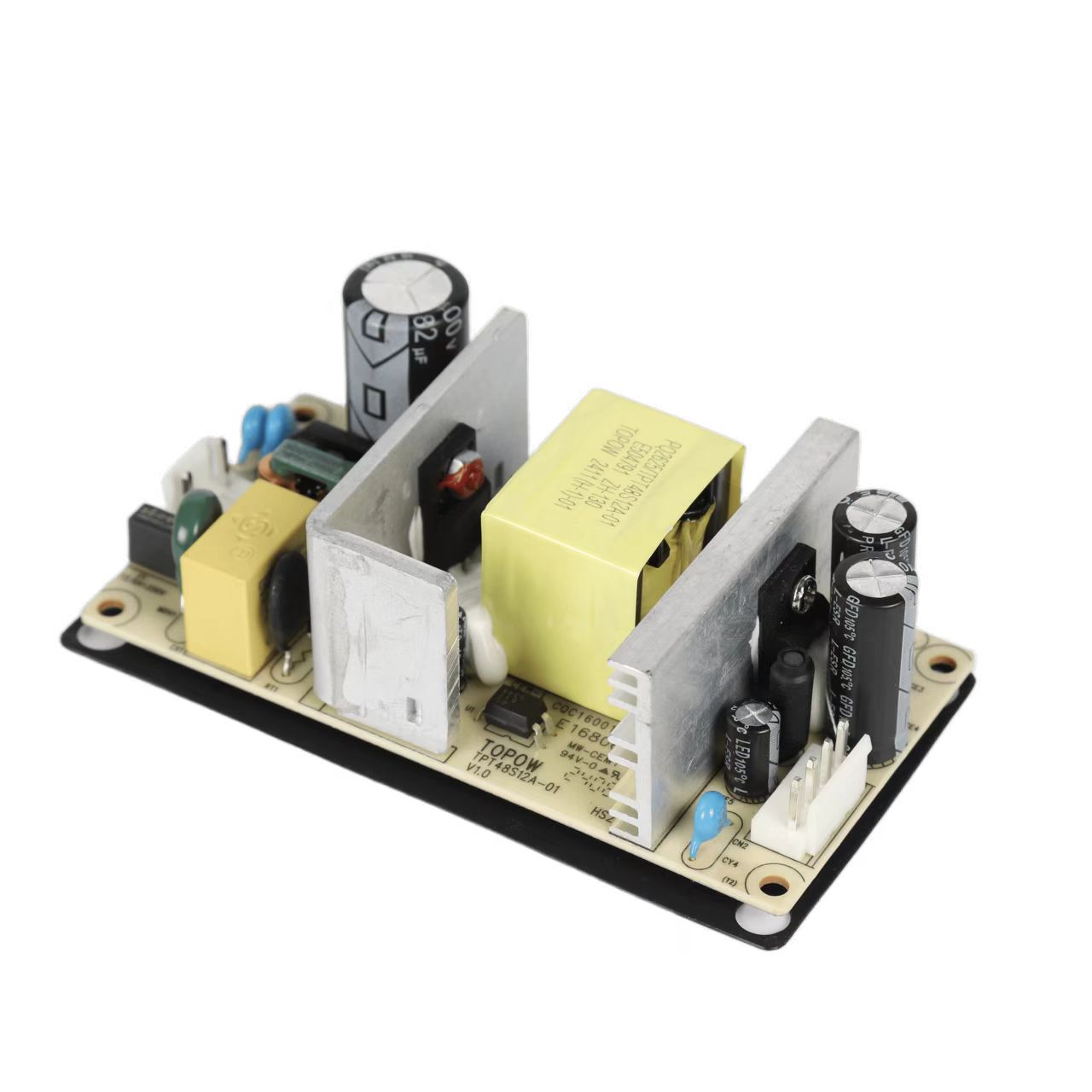
The basic working principle of RCC type suffix power adapter is shown in the figure below. The switching power tube Q1 and the pulse transformer T1 form a common intermittent oscillating circuit, R2 is the starting resistance, and C4 and C5 are positive feedback capacitive elements. After the circuit starts to oscillate, the secondary induction pulse of the transformer T1 is rectified by the rectifier diodes D4 and D5, and then filtered by the filter capacitors C2 and C6 to provide working voltage to the load equipment.
Read recommendations:
Do you really understand laptop batteries and power adapters?
The latest article
S series S1000 energy storage mobile power supply
2021-03-18S series S900 energy storage mobile power supply
2021-03-18New ABS Fire Shell Gigabit ESD Protection POE Powered Adapter Power Supply 90W POE Injector
2021-03-18165W Open Frame Power Supply
2021-03-18130W Open Frame Power Supply
2021-03-1880W Open Frame Power Supply
2021-03-1872W Open Frame Power Supply
2021-03-1872W Open Frame Power Supply
2021-03-1836W Open Frame Power Supply
2021-03-187W Open Frame Power Supply
2021-03-18Amplifier Power Supply
2021-03-1030W Amplifier Power Supply
2021-03-10144W Amplifier Power Supply
2021-03-1024W Adapter
2021-03-1018W Adapter
2021-03-1018W Adapter
2021-03-1018W Adapter
2021-03-10IEEE 802.3at 30W POE Power Supply
2021-03-1010W Open Frame Power Supply
2021-03-10450W Open Frame Power Supply
2021-03-09140W 55V 2.55A POE Power supply
2021-02-27The latest article
TOPOW to Showcase Power Solutions at Eletrolar Show 2026
2026-05-30Join TOPOW Electronics at SVIAZ 2026 in Moscow
2026-03-18Topow Electronics will attend to the Eletrolar Show, June 23th-26th 2025 in Brazil
2025-06-19Topow Electronics will attend to the Eletrolar Show, June 23th-26th 2025 in Brazil.
2025-06-19Topow will attend to Global Sources Consumer Electronics Show in April 11th-14th
2025-04-092003-2004
2025-03-252004-2006
2025-03-252006-2008
2025-03-252009-2011
2025-03-252012-2014
2025-03-252014-2017
2025-03-252018-2022
2025-03-252022-2024
2025-03-252024-2025
2025-03-25What are the types of mobile phone chargers and their functions?
2022-05-21Advantages of switching power adapters
2022-05-21Five core functions that the power adapter can achieve.adapter manufacture
2022-05-20Analysis of the importance of power adapters for notebooks.adapter Processor
2022-05-20Details of switching power supply in maintenance
2022-05-19Understand the precautions of the power adapter and be an expert in electricity safety
2022-05-19This is how the EMC interference of the switching power supply is generated.adapter wholesaler
2022-05-18The relationship between the nominal voltage and current of the power adapter.power adapter price
2022-05-18Five basic functions of notebook power adapters.adapter wholesaler
2022-05-17Lightning surge immunity test method.power adapter price
2022-05-17Switching power supply ripple source and control
2022-05-16Level 6 energy efficiency standard power adapter T series
2022-05-16Children sleeping with pacifiers are prone to tooth decay
2022-05-16Six methods to deal with the heating problem of switching power supply transformer
2022-05-14The principle of flyback switching power supply
2022-05-14Types of thermal protection for power adapters.adjustable power adapter
2022-05-13


About

Product
Process
News
Recruitment

 中文
中文 Online consultation
 Online map
 中
中