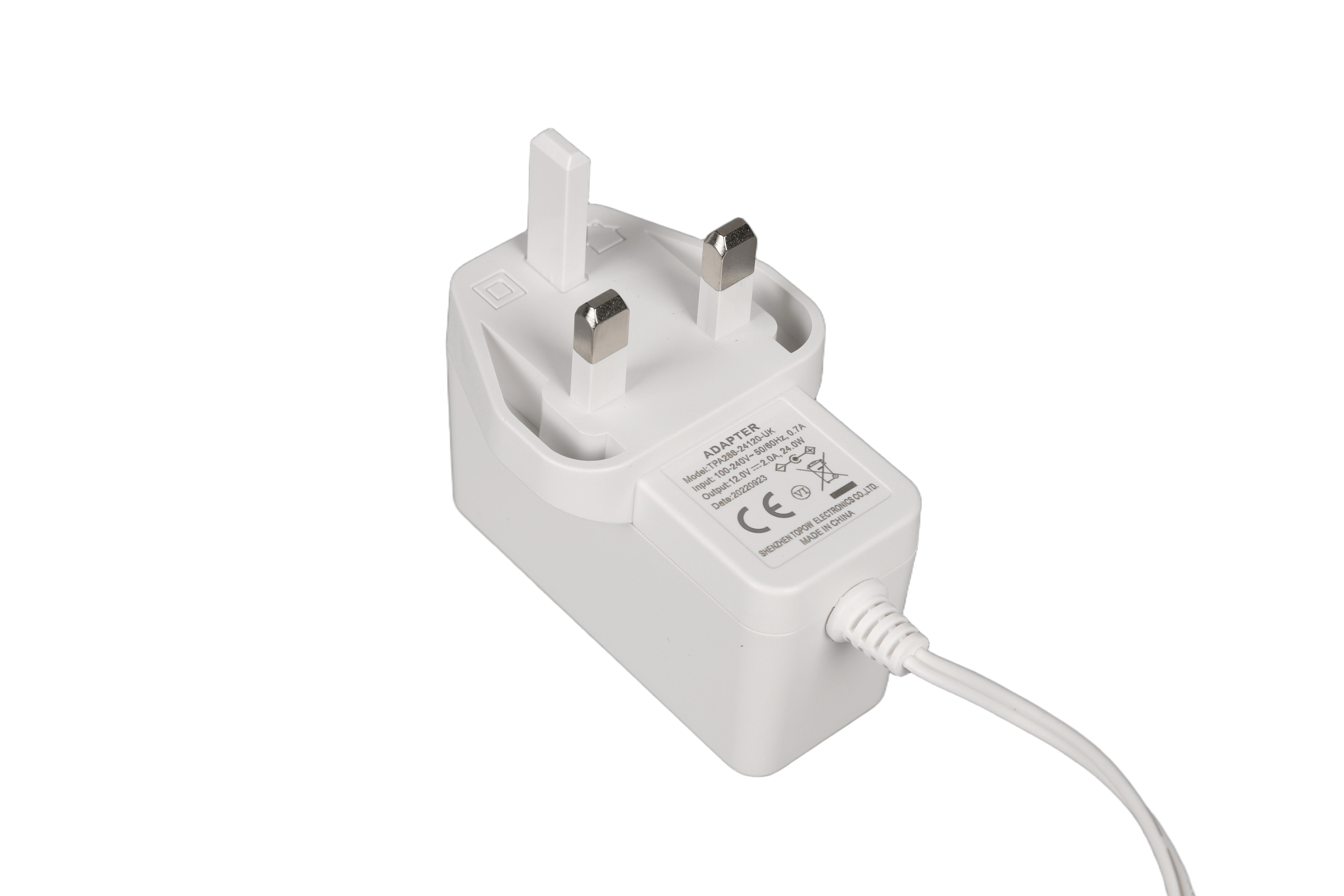
source:Industry News Popular:adapter release time:2021-05-27 09:47:12 Article author:sznbone
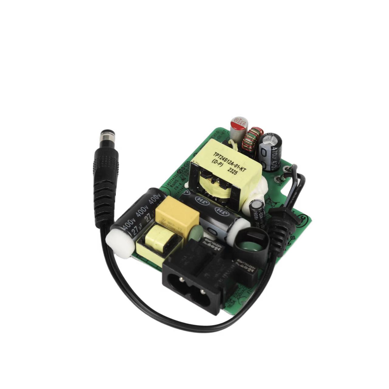
Introduction to commonly used capacitors
1. Ceramic Capacitors
Ceramic capacitors have strong insulation performance, high insulation resistance, can be used in high-voltage circuits, and have good heat resistance characteristics; ceramic materials have a wide range of temperature coefficients, and capacitors with different temperature coefficients can be produced to suit different applications. The loss tangent of ceramic capacitors has a very small relationship with frequency, and can be widely used in high-frequency circuits of switching power supplies. The capacitance of ceramic capacitors is relatively small, generally only a few picofarads to a few tenths of a microfarad. Ceramic capacitors are generally wafer-shaped, cylindrical or laminated. Low mechanical strength and easy breakage are the disadvantages of ceramic capacitors.
")
2. Film capacitors
Film capacitors are made of materials such as polystyrene, polytetrafluoroethylene, polypropylene or polycarbonate. Film capacitors are divided into polar organic film and non-polar organic film capacitors. Polar organic film capacitors have the advantages of large capacitance to volume ratio, high temperature resistance, and high voltage strength. Non-polar organic film capacitors have the advantages of small loss tangent, large insulation resistance, small dielectric absorption coefficient, and negative temperature coefficient. If a metal film is uniformly plated on one side of an organic film and then rolled to form a capacitor, it is called a metalized organic film capacitor. Film capacitors have cylindrical, flat, laminated block shapes and so on. In the product model of film capacitor, C means capacitor, and B means polystyrene. It is small in size, light in weight, and has a "self-healing" function.
Film capacitors include six types of film capacitors including polystyrene capacitors, polytetrafluoroethylene capacitors, polypropylene capacitors, polyester capacitors, and polycarbonate capacitors. Polystyrene film capacitors have the following characteristics:
a) Wide withstand voltage range, 30V~15KV. The working voltage of ordinary polystyrene capacitors is 100V, and the working voltage of high-voltage polystyrene capacitors can reach 10KV~15KV;
b) The insulation resistance is high, generally greater than or equal to 100000000000 ohms, so the leakage current is small. It can still maintain 95% of the charge after being charged for 1000 hours, while the low-quality capacitors are charged for 200 hours after being charged. Just put it all out
c) The tangent value of the loss angle is large, and metallized polystyrene capacitors should not be used in high-frequency circuits;
d) Capacitors have a wide capacity range, and can produce 100PF~100uF capacitors;
e) The accuracy of the capacitor is high, and it can produce 0.3%~0.1% high-precision capacitors;
f) The temperature coefficient is small, the performance is stable, acid and alkali resistance, moisture resistance, etc., pay attention to the marked withstand voltage and capacitance when using it.
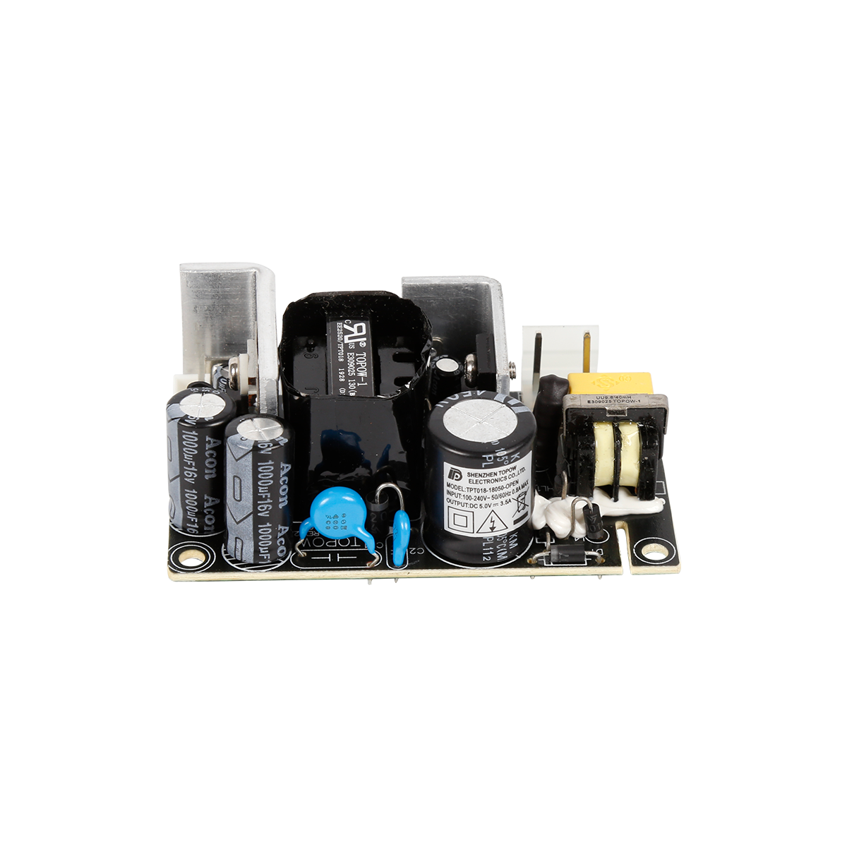
3. Electrolytic capacitor
Electrolytic capacitors have adopted many new technologies in the production process. Expand the etching rate of electrode foil, improve the chemical stability and thermal stability of the electrolyte film, develop high-conductivity electrolyte with good heat resistance, and use high-airtight heat-resistant sealing linings, etc. At present, the factors that affect the basic performance of aluminum electrolytic capacitors, such as the operating temperature, high-frequency impedance, and service life, are electrolyte. The sealing gasket of the capacitor plays an important role in controlling the drying of the electrolyte, so the gasket material has a great influence on the life of the aluminum electrolytic capacitor. The following parameters should be considered when choosing aluminum electrolytic capacitors: rated capacity, nominal temperature (generally 105°C), withstand voltage and leakage current. All aluminum electrolytic capacitors that can withstand various tests are rarely damaged in practical applications.
In this circuit, the peak collector current is determined by the selected emitter resistance and the clamping Zener voltage, and the maximum current limit during turn-off is no longer dependent on the transistor gain.
The whole working process of the circuit of the figure is as follows. Close the switch, the current flowing through R makes Q1 turn on, the positive feedback generated by P2 will strengthen the turn-on process, and Q1 enters the saturation state of full conduction.
The drive current loop established from P2 through R3, Q1 base-emitter junction, R1, and back through D2 is like a forward diode. The larger drive current value makes the transistor fully saturated during the entire turn-on period.
When Q1 is turned on, the collector current will increase with time, and its size is determined by the primary inductance, the converted secondary inductance L and the load.
As the current increases, the voltage across R1 and the base voltage of Q1 also increase until the Zener diode turns on.
Choose the value of R1 reasonably so that the drive current is cut off when the collector current reaches the maximum control value. At this time, the magnetic core just enters the saturation point, that is, the point S1' in the figure. Since H cannot be further increased when the clamping current is reached, the voltage across all windings must drop to zero. In the end, only a very small flyback is required to turn off Q1 and turn on Q2 and Q2 to continue to complete the work cycle. The collector limit current no longer depends on the transistor gain.
When the converted load current is lower than the magnetizing current, the diodes D5 and D6 connected to the collector provide a path for the reverse current. These two diodes work in a cross-connected manner. For example, when Q1 is turned off, the magnetizing current will quickly make the collector of Q1 positive. At the same time, the collector of Q2 quickly becomes negative until D6 is turned on. The dislocation effect provided by D6 makes the collector voltage of Q1 twice of Vcc. In order to reduce the shadow of leakage inductance, P1 and P3 should be wound with double strands.
In order to reduce radio frequency interference and secondary side breakdown stress, a buffer circuit is required in addition to D5 and D6.
In order to ensure a good switching effect, sufficient regenerative feedback is required, and P2 in the circuit shown should provide a driving voltage of at least 4 volts.
Read recommendations:
Reasons for Inrush Current in Switching Power Supply Design.adapter power manufacturer
The latest article
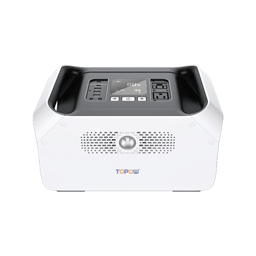
S series S1000 energy storage mobile power supply
2021-03-18S series S900 energy storage mobile power supply
2021-03-18New ABS Fire Shell Gigabit ESD Protection POE Powered Adapter Power Supply 90W POE Injector
2021-03-18165W Open Frame Power Supply
2021-03-18130W Open Frame Power Supply
2021-03-1880W Open Frame Power Supply
2021-03-1872W Open Frame Power Supply
2021-03-1872W Open Frame Power Supply
2021-03-1836W Open Frame Power Supply
2021-03-187W Open Frame Power Supply
2021-03-18Amplifier Power Supply
2021-03-1030W Amplifier Power Supply
2021-03-10144W Amplifier Power Supply
2021-03-1024W Adapter
2021-03-1018W Adapter
2021-03-1018W Adapter
2021-03-1018W Adapter
2021-03-10IEEE 802.3at 30W POE Power Supply
2021-03-1010W Open Frame Power Supply
2021-03-10450W Open Frame Power Supply
2021-03-09140W 55V 2.55A POE Power supply
2021-02-27The latest article
TOPOW to Showcase Power Solutions at Eletrolar Show 2026
2026-05-30Join TOPOW Electronics at SVIAZ 2026 in Moscow
2026-03-18Topow Electronics will attend to the Eletrolar Show, June 23th-26th 2025 in Brazil
2025-06-19Topow Electronics will attend to the Eletrolar Show, June 23th-26th 2025 in Brazil.
2025-06-19Topow will attend to Global Sources Consumer Electronics Show in April 11th-14th
2025-04-092003-2004
2025-03-252004-2006
2025-03-252006-2008
2025-03-252009-2011
2025-03-252012-2014
2025-03-252014-2017
2025-03-252018-2022
2025-03-252022-2024
2025-03-252024-2025
2025-03-25What are the types of mobile phone chargers and their functions?
2022-05-21Advantages of switching power adapters
2022-05-21Five core functions that the power adapter can achieve.adapter manufacture
2022-05-20Analysis of the importance of power adapters for notebooks.adapter Processor
2022-05-20Details of switching power supply in maintenance
2022-05-19Understand the precautions of the power adapter and be an expert in electricity safety
2022-05-19This is how the EMC interference of the switching power supply is generated.adapter wholesaler
2022-05-18The relationship between the nominal voltage and current of the power adapter.power adapter price
2022-05-18Five basic functions of notebook power adapters.adapter wholesaler
2022-05-17Lightning surge immunity test method.power adapter price
2022-05-17Switching power supply ripple source and control
2022-05-16Level 6 energy efficiency standard power adapter T series
2022-05-16Children sleeping with pacifiers are prone to tooth decay
2022-05-16Six methods to deal with the heating problem of switching power supply transformer
2022-05-14The principle of flyback switching power supply
2022-05-14Types of thermal protection for power adapters.adjustable power adapter
2022-05-13


About

Product
Process
News
Recruitment

 中文
中文 Online consultation
 Online map
 中
中