source:Industry News Popular:adapter release time:2021-05-11 09:11:11 Article author:sznbone
What are the functions of the resistors and capacitors on both sides of the crystal oscillator?
Scanner power adapter background knowledge
The crystal oscillator refers to a slice (referred to as a wafer) cut from a piece of quartz crystal at a certain azimuth angle. The quartz crystal resonator is referred to as quartz crystal or crystal or crystal oscillator; and the crystal element that adds IC inside the package to form an oscillator circuit is called Crystal oscillator. The charger is generally packaged in a metal shell, but also in a glass shell, ceramic or plastic package.
")
The general applications of crystal oscillators are:
1. A general-purpose crystal oscillator, used in various circuits to generate oscillation frequency.
2. Quartz crystal resonators for clock pulses are used in conjunction with other components to generate standard pulse signals, which are widely used in digital circuits.
3. Quartz crystal resonators for microprocessors.
4. CTVVTR uses quartz crystal resonator.
5. Quartz crystal oscillators for watches.
Today's problem
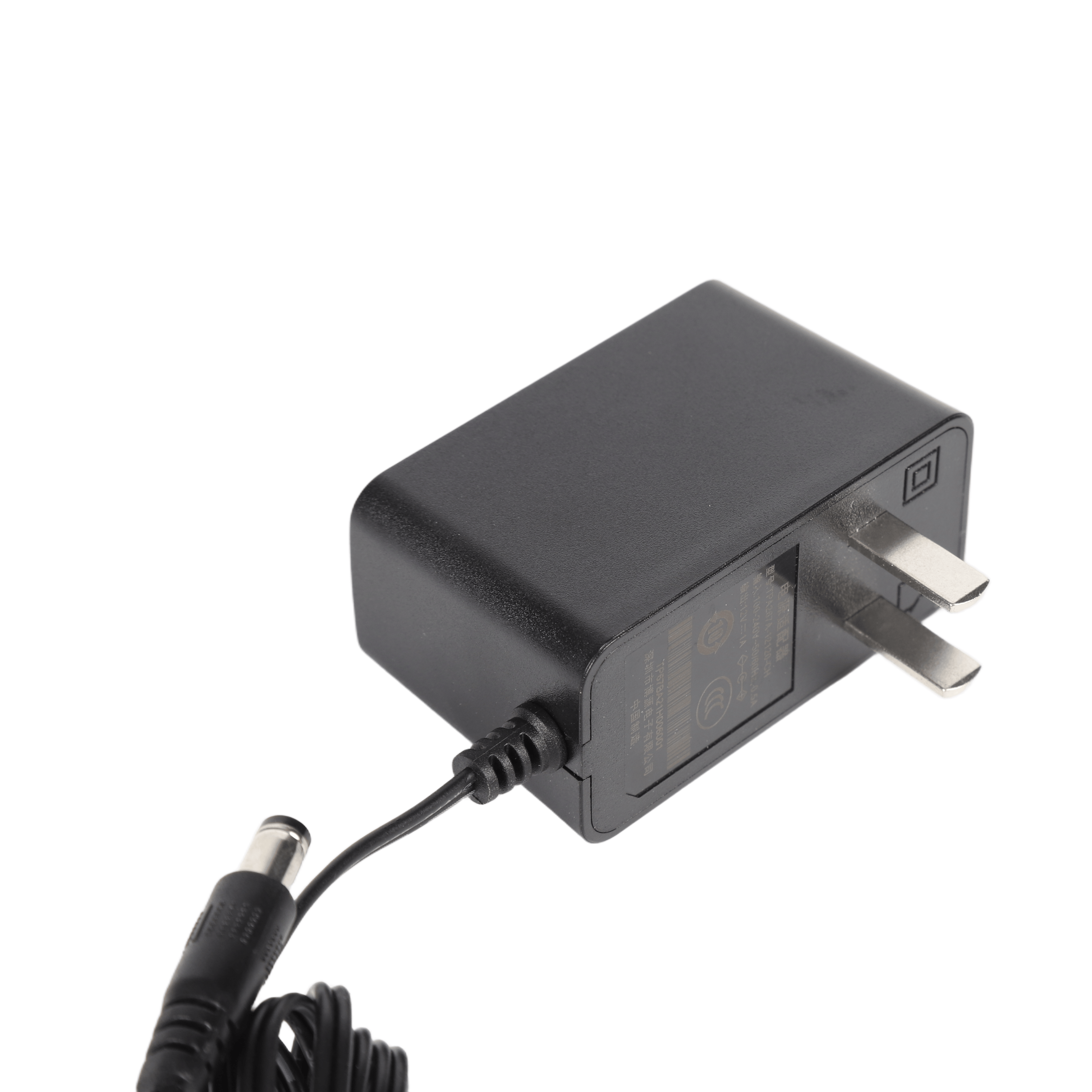
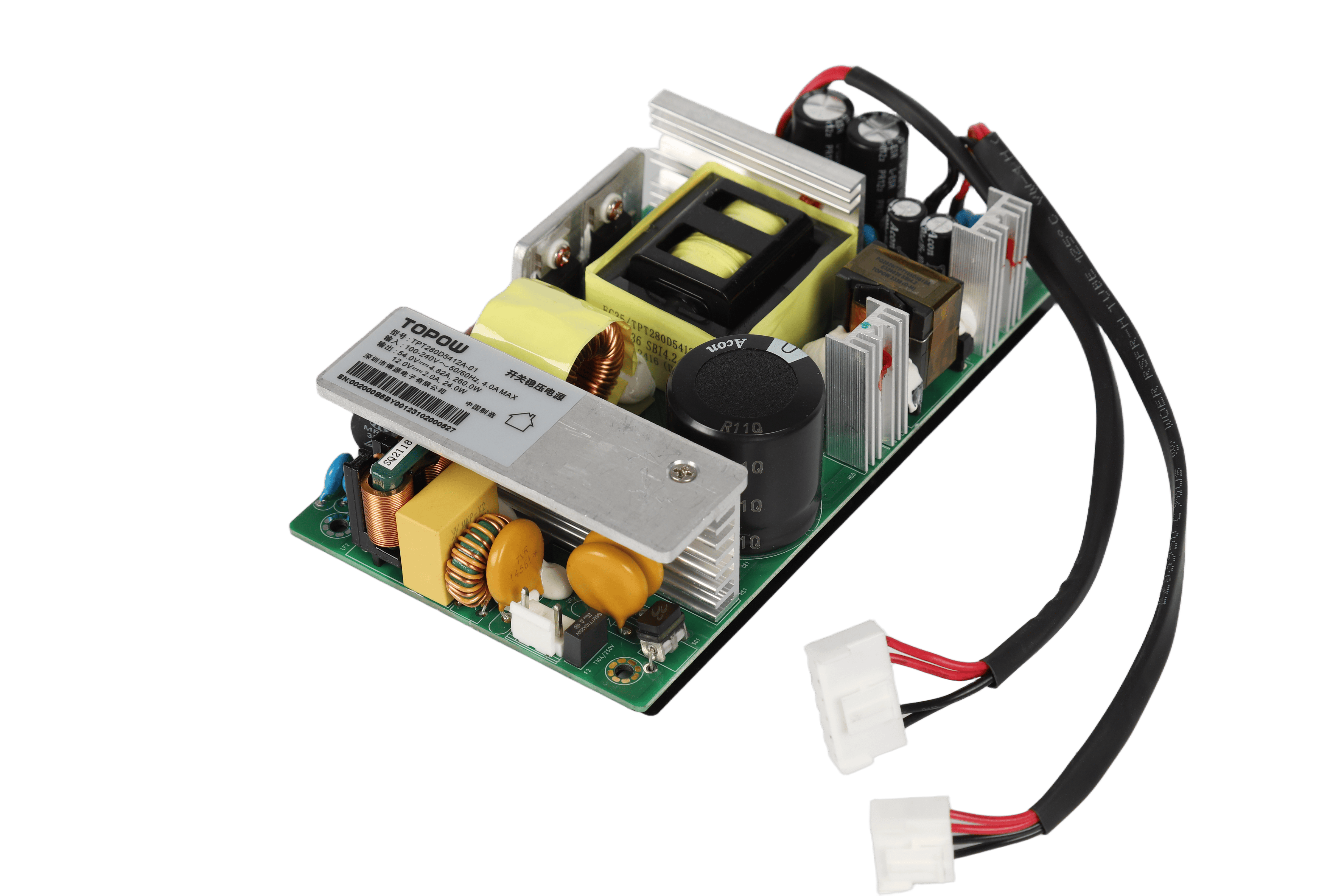
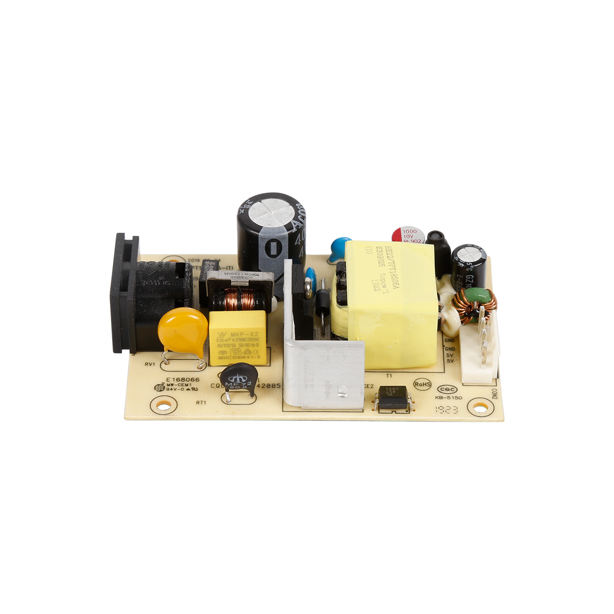
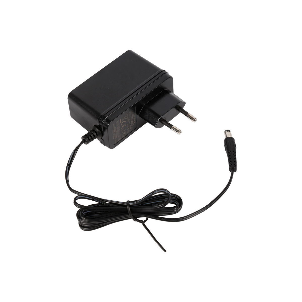
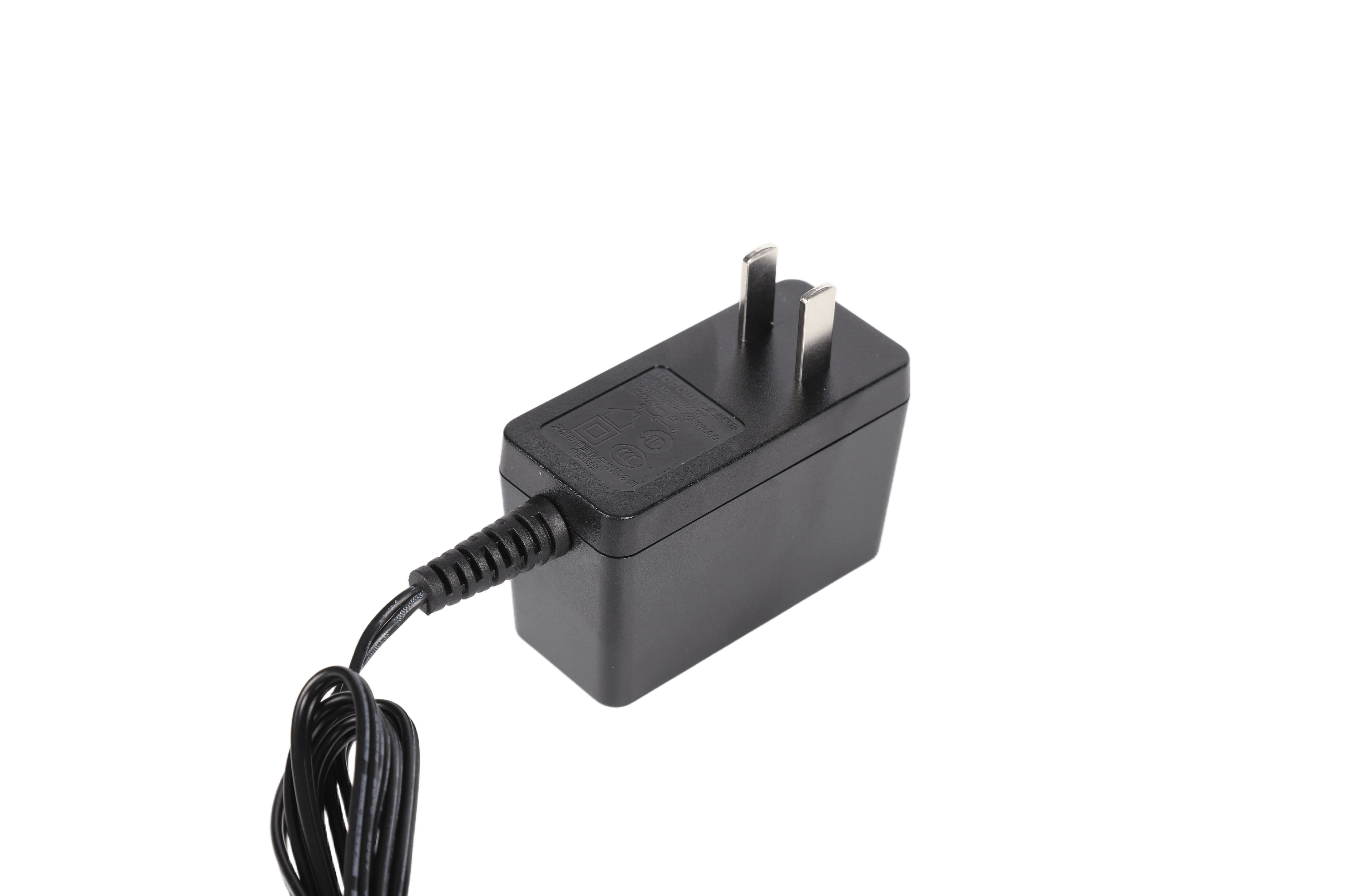
In the daily charger circuit design, we often use crystal oscillators, and we often see capacitors and resistors at both ends of the crystal oscillator, such as the two pictures below. So what are the functions of such capacitors and resistors? How are their values selected? You can combine theory and practical projects to give your own views.
Practical crowdfunding for Maxim chip design, led and initiated by the Fanyi Education Team, the current leader in PCB design training in China is coming! With the ultra-low power consumption, high-efficiency, highly integrated microcontroller MAX32660 as the core, a MAX32660 chip evaluation board (development board) is made, and the charger manufacturer will introduce and learn the whole process of "software and hardware design." "! Participate in the PCB design competition and have the opportunity to obtain the PcbLayout engineer certificate issued by the CEAC National Education Certification!
Inductance and chokes in chargers
The charger manufacturer introduced the following winding components (inductance and holding ring)
1. Simple inductance (no DC current through)
2. Common-mode line filter inductance (especially dual-winding inductance with large symmetrical power frequency current)
3. Series line filter inductor (inductance carrying large and asymmetric power frequency current)
4. Flow coil (inductance wrapped around a ferrite core with an air gap and carrying a large DC bias current)
5. Rod-shaped flow ring (a flow-throwing ring wound on a ferrite core or a rod-shaped iron powder core)
In order to facilitate the discussion, the "inductance" we are talking about here refers to the winding components without DC current, and the "choke coil" refers to the winding components with large bias current and relatively small AC ripple.
The design and material selection of winding components must fully consider the place of application. In addition, the design must be repeated many times, and the relationship between some interconnected but opposite variables must be coordinated.
If the engineer can fully understand and grasp the theoretical and actual specifications required for the optimal design of various winding components in the charger, then the design skills he possesses will be precious and unique.
The design method used here is mainly based on its scope of application, focusing on the three aspects of cost, size and loss. The final design can only be a compromise solution. Since these three main aspects are contradictory, it can only be used. A compromise solution. The task of the designer is to obtain the best compromise.
In charger applications, inductors without DC bias are generally limited to low-pass filters used in the charger circuit. Here, their main function is to prevent high noise from being transmitted back to the charger circuit. For this type of application, we should choose a core material with a high conductivity.
Chokes (inductors carrying large bias DC currents) are used in high-frequency power output filters and continuous buck-boost converter "transformers". In these applications, low permeability and high frequency should be preferred Magnetic core material with low magnetic loss.
In order to reduce the number of turns and reduce the copper loss, the most ideal core material should have high permeability and small magnetic loss. Unfortunately, in the design of the current-carrying circle, the existence of large DC components and the actual use The limited saturation magnetic flux density of magnetic materials makes us have to choose low-conductivity materials or introduce air into the core. However, due to the too low effective permeability, more windings are required to achieve the required inductance. value. Therefore, in the choke coil design, in order to pass a larger DC current, both low copper loss and high efficiency must be taken into account.
Simple inductor
In the application field of charger, pure inductance (cannot carry DC current component or forced AC high current component) is rare. Unlike the common-mode filter inductors that will be introduced below, since no air gap is required, the value of this inductance can be obtained directly from the given core inductance A value, so the design is relatively simple, and this will not be described. But it must be remembered that the size of this type of inductance is proportional to the square of the number of turns. Therefore, A1 must be given for 1 turn (as shown in the following formula), or A1 for multiple turns must be given. At this time, the value of A should be reduced to the value of 1 turn by dividing by the square of the number of turns.
L=N2AL
Read recommendations:
S series S900 energy storage mobile power supply
Introduction to commonly used capacitors
Technical characteristics of full-bridge push-pull converter
The latest article
S series S1000 energy storage mobile power supply
2021-03-18S series S900 energy storage mobile power supply
2021-03-18New ABS Fire Shell Gigabit ESD Protection POE Powered Adapter Power Supply 90W POE Injector
2021-03-18165W Open Frame Power Supply
2021-03-18130W Open Frame Power Supply
2021-03-1880W Open Frame Power Supply
2021-03-1872W Open Frame Power Supply
2021-03-1872W Open Frame Power Supply
2021-03-1836W Open Frame Power Supply
2021-03-187W Open Frame Power Supply
2021-03-18Amplifier Power Supply
2021-03-1030W Amplifier Power Supply
2021-03-10144W Amplifier Power Supply
2021-03-1024W Adapter
2021-03-1018W Adapter
2021-03-1018W Adapter
2021-03-1018W Adapter
2021-03-10IEEE 802.3at 30W POE Power Supply
2021-03-1010W Open Frame Power Supply
2021-03-10450W Open Frame Power Supply
2021-03-09140W 55V 2.55A POE Power supply
2021-02-27The latest article
TOPOW to Showcase Power Solutions at Eletrolar Show 2026
2026-05-30Join TOPOW Electronics at SVIAZ 2026 in Moscow
2026-03-18Topow Electronics will attend to the Eletrolar Show, June 23th-26th 2025 in Brazil
2025-06-19Topow Electronics will attend to the Eletrolar Show, June 23th-26th 2025 in Brazil.
2025-06-19Topow will attend to Global Sources Consumer Electronics Show in April 11th-14th
2025-04-092003-2004
2025-03-252004-2006
2025-03-252006-2008
2025-03-252009-2011
2025-03-252012-2014
2025-03-252014-2017
2025-03-252018-2022
2025-03-252022-2024
2025-03-252024-2025
2025-03-25What are the types of mobile phone chargers and their functions?
2022-05-21Advantages of switching power adapters
2022-05-21Five core functions that the power adapter can achieve.adapter manufacture
2022-05-20Analysis of the importance of power adapters for notebooks.adapter Processor
2022-05-20Details of switching power supply in maintenance
2022-05-19Understand the precautions of the power adapter and be an expert in electricity safety
2022-05-19This is how the EMC interference of the switching power supply is generated.adapter wholesaler
2022-05-18The relationship between the nominal voltage and current of the power adapter.power adapter price
2022-05-18Five basic functions of notebook power adapters.adapter wholesaler
2022-05-17Lightning surge immunity test method.power adapter price
2022-05-17Switching power supply ripple source and control
2022-05-16Level 6 energy efficiency standard power adapter T series
2022-05-16Children sleeping with pacifiers are prone to tooth decay
2022-05-16Six methods to deal with the heating problem of switching power supply transformer
2022-05-14The principle of flyback switching power supply
2022-05-14Types of thermal protection for power adapters.adjustable power adapter
2022-05-13


About

Product
Process
News
Recruitment

 中文
中文 Online consultation
 Online map
 中
中