source:Industry News Popular:adapter release time:2022-01-26 09:16:10 Article author:sznbone
")
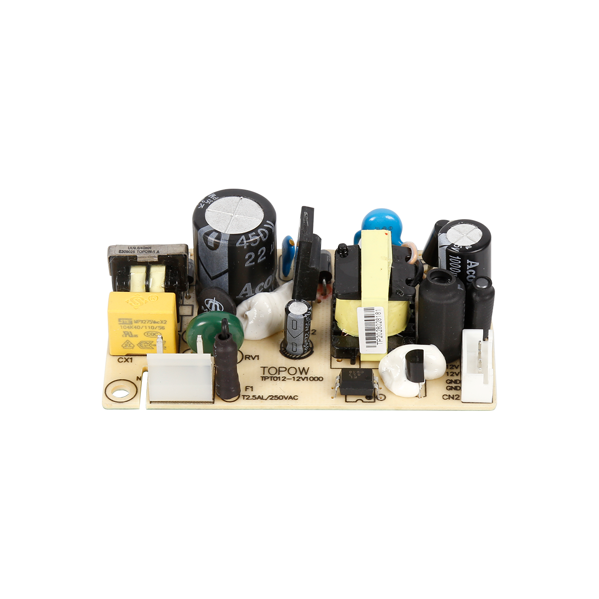
At present, the high-frequency power adapter modules produced by domestic power adapter manufacturers have generally low single-unit power. They are used in small-capacity DC systems. The performance-price ratio is absolutely dominant and the reliability is relatively high. For large-capacity DC systems, they must be connected in parallel. Many modules. In this way, on the one hand, the reliability of the DC system is greatly reduced; on the other hand, the cost is increased. The power adapter introduced in this section is designed to solve these two problems.
1. Control circuit
This power control circuit uses the TL494 chip produced by Motorola. Its internal structure block diagram is shown in Figure 813, and its main pin functions are as follows.
⑩Pin: connect to the positive terminal of the power supply, the voltage range is 7~40V.
⑦Foot: public negative terminal.
④Pin: output 5V reference voltage.
⑥Pin: external timing resistor R1, often more than several thousand ohms.
⑤Pin: external timing capacitor C, generate sawtooth wave voltage and send it to comparator and dead time comparator, the oscillation frequency is f=1/(R2C1).
④Foot: Dead time control, the input DC voltage is 0~4V, and the duty cycle of TL494 output pulse is controlled (0.45~0). On this basis, the duty cycle is also controlled by the feedback signal. ④The foot is also often used as a soft start Control terminal, make the output pulse width gradually reach the design value from 0 ③Pin: output mode control, when U13=0, it is used to drive single-ended circuit.
The TL494 contains two identical error amplifiers. Their output terminals are isolated by diodes and sent to the non-inverting terminal of the comparator. They are compared with the sawtooth voltage at the inverting terminal and determine the width of the output voltage. The voltage to
The control can also be controlled by the error amplifier separately. The two amplifiers are used independently for feedback voltage and overcurrent protection. ③The pin is connected to the RC network to improve the stability of the entire circuit. TL494 is a fixed frequency PWM control The circuit is suitable for the design of all (single-ended or double-ended) power adapter typical circuits. Its main performance is as follows: ①The input voltage is DC7~40V, and the unregulated power supply can be used as the input power supply, so that the auxiliary power supply simplifies the two final stages of TL494 When only the power tube is working in the range of 7~40V, the maximum output current can reach 250mA. Therefore, its load capacity is strong, and it can work in push-pull mode, or it can work in parallel with two outputs, and it can be directly driven at low power.
②There is a 12V power adapter reference voltage inside, which is easy to use. When the reference voltage is short-circuited, there is a droop protection feature
③There is a pair of operational amplifiers inside, which can be used as feedback amplifiers and protection, and the control is very convenient
④In the high-frequency power adapter, the output square wave must be symmetrical. In some other applications, the square wave needs to be artificially asymmetry, that is, the duty cycle of the square wave needs to be controlled. Control, not only can adjust the duty cycle, but also can be used as output soft-start protection
⑤You can choose single-ended, parallel and alternate output methods
The power adapter manufacturer can see from Figure 8-13: the pins ① and ② of the TL494 chip are the input terminals of the operational amplifier, the circuit is used for voltage feedback, the pin ① is used for feedback input, and the pin ② is connected to the pin ④ through a resistor. The internal reference voltage (5V) takes the divided voltage and serves as the reference for comparison with pin ①. Pin ③ is used for compensation and correction. It is the input of the PWM comparator, and the resistance and capacitance can be connected to suppress oscillation. Pin ④ is the dead zone control terminal, which is added to The higher the voltage on pin ④, the greater the width of the dead zone. When it is grounded, the dead zone is zero, that is, full output; when it is connected to a 5V voltage, the dead zone is the largest and no output pulse. Use this feature to ④ There is a capacitor indirectly with pin ⑩, which can achieve the purpose of output soft start, and can also be used for short circuit protection. Pin ⑤ and pin ⑥ are connected to the grounding capacitor and resistance of the oscillator. The oscillation frequency of the circuit oscillator is 50kHz. Pin ⑩ is connected to the internal Reference voltage +5V. Pin ⑩ and pin ⑩ are connected to the input of another operational amplifier. The circuit is used for current feedback and current protection. When not in use, pin ① and pin ⑩ can be shorted to ground
Read recommendations:
The latest article
S series S1000 energy storage mobile power supply
2021-03-18S series S900 energy storage mobile power supply
2021-03-18New ABS Fire Shell Gigabit ESD Protection POE Powered Adapter Power Supply 90W POE Injector
2021-03-18165W Open Frame Power Supply
2021-03-18130W Open Frame Power Supply
2021-03-1880W Open Frame Power Supply
2021-03-1872W Open Frame Power Supply
2021-03-1872W Open Frame Power Supply
2021-03-1836W Open Frame Power Supply
2021-03-187W Open Frame Power Supply
2021-03-18Amplifier Power Supply
2021-03-1030W Amplifier Power Supply
2021-03-10144W Amplifier Power Supply
2021-03-1024W Adapter
2021-03-1018W Adapter
2021-03-1018W Adapter
2021-03-1018W Adapter
2021-03-10IEEE 802.3at 30W POE Power Supply
2021-03-1010W Open Frame Power Supply
2021-03-10450W Open Frame Power Supply
2021-03-09140W 55V 2.55A POE Power supply
2021-02-27The latest article
TOPOW to Showcase Power Solutions at Eletrolar Show 2026
2026-05-30Join TOPOW Electronics at SVIAZ 2026 in Moscow
2026-03-18Topow Electronics will attend to the Eletrolar Show, June 23th-26th 2025 in Brazil
2025-06-19Topow Electronics will attend to the Eletrolar Show, June 23th-26th 2025 in Brazil.
2025-06-19Topow will attend to Global Sources Consumer Electronics Show in April 11th-14th
2025-04-092003-2004
2025-03-252004-2006
2025-03-252006-2008
2025-03-252009-2011
2025-03-252012-2014
2025-03-252014-2017
2025-03-252018-2022
2025-03-252022-2024
2025-03-252024-2025
2025-03-25What are the types of mobile phone chargers and their functions?
2022-05-21Advantages of switching power adapters
2022-05-21Five core functions that the power adapter can achieve.adapter manufacture
2022-05-20Analysis of the importance of power adapters for notebooks.adapter Processor
2022-05-20Details of switching power supply in maintenance
2022-05-19Understand the precautions of the power adapter and be an expert in electricity safety
2022-05-19This is how the EMC interference of the switching power supply is generated.adapter wholesaler
2022-05-18The relationship between the nominal voltage and current of the power adapter.power adapter price
2022-05-18Five basic functions of notebook power adapters.adapter wholesaler
2022-05-17Lightning surge immunity test method.power adapter price
2022-05-17Switching power supply ripple source and control
2022-05-16Level 6 energy efficiency standard power adapter T series
2022-05-16Children sleeping with pacifiers are prone to tooth decay
2022-05-16Six methods to deal with the heating problem of switching power supply transformer
2022-05-14The principle of flyback switching power supply
2022-05-14Types of thermal protection for power adapters.adjustable power adapter
2022-05-13


About

Product
Process
News
Recruitment

 中文
中文 Online consultation
 Online map
 中
中